
Related Manuals for NETGEAR FE104 - Hub

Summary of Contents for NETGEAR FE104 - Hub
- Page 1 Installation Guide for the Model FE104 and Model FE108 Fast Ethernet Hubs NETGEAR, Inc. 4500 Great America Parkway Santa Clara, CA 95054 Phone: 1-888-NETGEAR E-mail: support@NETGEAR.com www.NETGEAR.com M-FE100NA-1 September 2000...
- Page 2 In the interest of improving internal design, operational function, and/or reliability, NETGEAR reserves the right to make changes to the products described in this document without notice. NETGEAR does not assume any liability that may occur due to the use or application of the product(s) or circuit layout(s) described herein.
- Page 3 +1 801-236-8499 World Wide Web NETGEAR maintains a World Wide Web Home Page that you can access at the universal resource locator (URL) http://www.NETGEAR.com. A direct connection to the Internet and a Web browser such as Mosaic or Netscape are required.
-
Page 5: Table Of Contents
Normal/Uplink Push Button ..................2-4 Rear Panel ........................2-5 Chapter 3 Installation Preparing the Site ......................3-1 Checking Package Contents ..................3-2 Installing a NETGEAR 100BASE-TX Hub ..............3-3 Installing the Hub on a Flat Surface .................3-3 Installing Multiple Hubs ....................3-4 Verifying Your Installation ....................3-6 Chapter 4 Troubleshooting Troubleshooting the Hub and the Network ..............4-1... - Page 6 Appendix A Technical Specifications General Specifications ....................A-1 Appendix B RJ-45 Connector Information Appendix C Fast Ethernet and Cabling Guidelines Fast Ethernet Technology ....................C-1 Fast Ethernet Cabling ....................C-2 Cable Guidelines ..................... C-2 Cable Lengths ......................C-3 Cable Specifications ....................C-3 Twisted Pair Cables ....................
- Page 7 Figures Figure 2-1. Front panel of the Model FE104 Fast Ethernet Hub ........2-1 Figure 2-2. Front panel of the Model FE108 Fast Ethernet Hub ........2-2 Figure 2-3. Link/Rx and Part (partition) LEDs on the RJ-45 ports ......2-4 Figure 2-4. Normal/Uplink push button ..............2-4 Figure 2-5.
- Page 8 viii Figures...
- Page 9 Tables Table 2-1. LED descriptions ..................2-3 Table 3-1. Operating environment requirements ............3-1 Table 4-1. Troubleshooting ..................4-1 Table B-1. RJ-45 connector pinouts ................. B-2 Table C-1. Electrical requirements of Category 5 cable ........... C-3 Tables...
- Page 11 Model FE104 4-port Fast Ethernet Hub or ™ the NETGEAR Model FE108 8-port Fast Ethernet Hub. Both hubs are IEEE 802.3u-based Class II repeaters that provide you with a low-cost, high-performance network solution and are designed to support power workgroups operating at 100 Mbps.
-
Page 12: Introduction
Installation Guide for the Model FE104 and Model FE108 Fast Ethernet Hubs Features The Model FE104 and Model FE108 hubs have the following key features: • IEEE 802.3u standard compliance allows interoperation with all 100BASE-TX Fast Ethernet (100 Mbps) products. •... -
Page 13: Physical Description
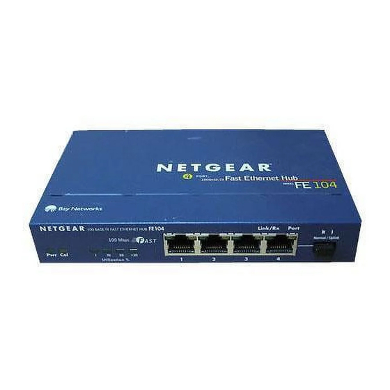
Chapter 2 Physical Description This chapter is divided into sections on the front and rear panel components of the Model FE104 and Model FE108 hubs. Use the key at the bottom of each illustration to identify the associated component. Front Panel The front panel contains the LEDs, RJ-45 100BASE-TX port connectors, and Normal/Uplink push button. -
Page 14: Led Display
Installation Guide for the Model FE104 and Model FE108 Fast Ethernet Hubs 100BASE-TX FAST ETHERNET HUB FE108 Link/Rx Part 100 Mbps F AST Normal/Uplink >30 Utilization % 185EA Key: 1 = Pwr (power) LED 2 = Col (collision) LED 3 = Utilization % LEDs 4 = RJ-45 ports with Link/Rx and Part (partition) LEDs on each port 5 = Normal/Uplink push button Figure 2-2. -
Page 15: Rj-45 100Base-Tx Ports
Installation Guide for the Model FE104 and Model FE108 Fast Ethernet Hubs Table 2-1 describes each LED on the front panel of the hub. Table 2-1. LED descriptions Label Color Activity Description Green Power is supplied to the hub. Yellow Blinking There is data collision on the network. -
Page 16: Normal/Uplink Push Button
Installation Guide for the Model FE104 and Model FE108 Fast Ethernet Hubs As illustrated in Figure 2-3, two LEDs are positioned at the top corners of each RJ-45 connector. The left indicator is the Link/Rx (receive) LED, and the right indicator is the Part (partition) LED. Both LEDs are described in Table 2-1. -
Page 17: Rear Panel
Installation Guide for the Model FE104 and Model FE108 Fast Ethernet Hubs The Normal/Uplink push button eliminates the need to use a crossover cable for daisy-chaining or cascading. Use the following guidelines to configure Ports 4 and 8 for uplink or normal wiring: •... -
Page 18: Figure 2-6. Rear Panel Of The Model Fe108 Hub
Installation Guide for the Model FE104 and Model FE108 Fast Ethernet Hubs 12 Vdc 1.2A – 182EA Key: 1 = Grounding clip 2 = DC power receptacle Figure 2-6. Rear panel of the Model FE108 hub Physical Description... -
Page 19: Installation
• Preparing the site • Checking package contents • Installing a NETGEAR 100BASE-T hub • Verifying your installation Preparing the Site Before you begin installing the hub, prepare the installation site. Make sure the operating environment meets the physical requirements of the equipment as listed in Table 3-1. -
Page 20: Checking Package Contents
Keep the carton, including the original packing materials. Use them to repack the hub if you need to return it for repair. To qualify for product updates and product warranty registrations, complete the Warranty and Owner Registration Card within 30 days of purchase and return it to NETGEAR, Inc. Installation... -
Page 21: Installing A Netgear 100Base-Tx Hub
Installation Guide for the Model FE104 and Model FE108 Fast Ethernet Hubs Installing a NETGEAR 100BASE-TX Hub This section provides information and instructions for installing the hub on a tabletop or any other flat surface. For instructions on installing more than one hub, see “Installing Multiple Hubs” later in this chapter. -
Page 22: Installing Multiple Hubs
Installation Guide for the Model FE104 and Model FE108 Fast Ethernet Hubs Installing Multiple Hubs This section provides you with information about installing multiple hubs. As illustrated in Figure 3-1, two hubs can be simply daisy-chained together. In Figure 3-2, multiple hubs are connected to a server through the Model FS104 10/100 Mbps Fast Ethernet Switch. -
Page 23: Figure 3-2. Connecting Multiple Hubs
Installation Guide for the Model FE104 and Model FE108 Fast Ethernet Hubs Model FS104 switch Model FE104 hub Model FE108 hub Model EN108 hub 199EA Key: 1 = 100 Mbps connection 2 = Server 3 = FS104 10/100 Mbps switch (Normal/Uplink push button set in Normal position) 4 = 10 Mbps connection 5 = PCs with 100 Mbps connection to Fast Ethernet hub 6 = PCs with 10 Mbps connection to Ethernet hub... -
Page 24: Verifying Your Installation
Installation Guide for the Model FE104 and Model FE108 Fast Ethernet Hubs Verifying Your Installation When installation is complete and power has been applied to the hub, the following conditions should exist: • The Pwr (power) LED on the front panel is on. •... -
Page 25: Troubleshooting
Chapter 4 Troubleshooting This chapter provides information about troubleshooting the Model FE104 and Model FE108 hubs. Troubleshooting the Hub and the Network To troubleshoot the hub and the network, refer to Table 4-1. Table 4-1. Troubleshooting Symptom Activity Check No power at hub Pwr (power) LED off Check the power cord connections and make sure the ends are properly plugged into the hub and the wall outlet. - Page 26 Installation Guide for the Model FE104 and Model FE108 Fast Ethernet Hubs Table 4-1. Troubleshooting (continued) Symptom Activity Check Port connection not Link/Rx LED off Make sure that the network adapter card installed in the PC functioning or intermittent is in working condition and that the computer and hub are turned on.
-
Page 27: Network Configuration
This chapter provides an overview of the levels of service that are provided by incorporating NETGEAR Ethernet hubs and switches into your network. Examples are given to illustrate the function of the hubs and switches in several configurations that provide those different levels of service to network users. -
Page 28: 100Base-Tx Shared Repeater
Ethernet network, isolated from the 10 Mbps network users who need occasional server access. By adding a NETGEAR Model SW502 Ethernet Switch that has one 10 Mbps port and one 100 Mbps port, the existing 10 Mbps users can access the server through the 100 Mbps port on the Model SW502 switch. -
Page 29: Figure 5-2. Using The Model Fe104 Hub To Migrate Your Network To 100 Mbps
Installation Guide for the Model FE104 and Model FE108 Fast Ethernet Hubs Model FE104 hub Model SW502 switch Model EN516 hub Model EN516 hub Model EN516 hub 217EA Key: 1 = PCs with 100 Mbps connections 2 = 100 Mbps connection 3 = Model FE104 Fast Ethernet Hub (Normal/Uplink push button set in Normal position) 4 = Server 5 = Model SW502 switch (Normal/Uplink push button set in Uplink position on port connected to Model FE104 Fast... -
Page 30: Multiport Switch With Fast Ethernet Backbone
Installation Guide for the Model FE104 and Model FE108 Fast Ethernet Hubs Multiport Switch with Fast Ethernet Backbone If the 10 Mbps shared repeater portion of the network experiences congestion, you can use the Model SW507 Ethernet Switch with six 10 Mbps ports and one 100 Mbps port to segment the 10 Mbps traffic on the hubs. -
Page 31: Technical Specifications
Appendix A Technical Specifications This appendix provides technical specifications for the NETGEAR Model FE104 and Model FE108 Fast Ethernet Hubs. General Specifications Network Protocol and Standards Compatibility IEEE 802.3u 100BASE-TX, Fast Ethernet IEEE 802.3 CSMA/CD Data Rate 100 Mbps with 4B/5B encoding and MLT-3 physical interface for 100BASE-TX... - Page 32 Installation Guide for the Model FE104 and Model FE108 Fast Ethernet Hubs Environmental Specifications Operating temperature: 0 C to 40 C (32 F to 104 F) Storage temperature: –25 C to 70 C (–13 F to 158 F) Operating humidity: 80% maximum relative humidity, noncondensing Storage humidity: 95% maximum relative humidity, noncondensing...
-
Page 33: Rj-45 Connector Information
Appendix B RJ-45 Connector Information This appendix provides information about the RJ-45 connectors used for the Model FE104 and Model FE108 Fast Ethernet Hubs. The IEC 603-7 8-pin modular connector, commonly called an RJ-45 connector, is used to connect stations, hubs, and switches through unshielded twisted pair (UTP) cable and supports 100 Mbps data transmission. - Page 34 Installation Guide for the Model FE104 and Model FE108 Fast Ethernet Hubs Table B-1. RJ-45 connector pinouts Normal (MDI-X) Uplink (MDI) * Input Receive Data + Output Transmit Data + Input Receive Data - Output Transmit Data - Output Transmit Data + Input Receive Data + Output Transmit Data - Input Receive Data -...
-
Page 35: Fast Ethernet And Cabling Guidelines
Appendix C Fast Ethernet and Cabling Guidelines This appendix discusses the Fast Ethernet technology and the cable specifications and guidelines for Category 5 UTP cabling. Fast Ethernet Technology Fast Ethernet is conventional Ethernet but faster. Fast Ethernet, or 100BASE-TX, operates at 100 Mbps instead of 10 Mbps. -
Page 36: Fast Ethernet Cabling
Installation Guide for the Model FE104 and Model FE108 Fast Ethernet Hubs Fast Ethernet Cabling In a Fast Ethernet network, certain rules and regulations must be followed. This section discusses the following aspects of cabling: • Cable guidelines • Cable lengths within a network •... -
Page 37: Cable Lengths
Installation Guide for the Model FE104 and Model FE108 Fast Ethernet Hubs Cable Lengths Category 5 distributed cable that meets ANSI/EIA/TIA-568-A building wiring standards can be a maximum of 328 feet (100 m) in length, divided as follows: • 20 feet (6 m) between the hub and the patch panel (if used) •... -
Page 38: Twisted Pair Cables
Installation Guide for the Model FE104 and Model FE108 Fast Ethernet Hubs Twisted Pair Cables For two devices to communicate, the transmitter of each device must be connected to the receiver of the other device. The crossover function is usually implemented internally as part of the circuitry in the device. -
Page 39: Patch Panels And Cables
Installation Guide for the Model FE104 and Model FE108 Fast Ethernet Hubs Patch Panels and Cables If you are using patch panels, make sure that they meet the 100BASE-T requirements. NETGEAR recommends Category 5 UTP cable for all patch cables and work area cables to ensure that your UTP patch cable rating meets or exceeds the distribution cable rating. -
Page 41: Index
Index Numerics 100BASE-T hub installation 3-3 Ethernet cabling guidelines C-2 technology C-1 access requirements 3-1 features 1-2 cable front panel Category 5 UTP 5-1 Model FE104 hub 2-1 Category 5 UTP, troubleshooting 4-1 Model FE108 hub 2-2 crossover 2-5 guidelines C-3 specifications (table) C-3 straight-through 2-5 humidity requirements 3-1... - Page 42 Installation Guide for the Model FE104 and Model FE108 Fast Ethernet Hubs LEDs package contents 3-2 Col (collision) 2-3 Part (partition) LED 2-3 description (table) 2-3 patch panel C-3 Link/Rx 2-3 Port 4 Link/Rx, troubleshooting 4-2 configuring 2-4 overview 1-2 pinout information (table) B-2 Part (partition) 2-3 troubleshooting 4-2...
- Page 43 Installation Guide for the Model FE104 and Model FE108 Fast Ethernet Hubs site preparation 3-1 straight-through cable 2-5 technical specifications A-1 temperature requirements 3-1 troubleshooting COL LED blinking 4-2 Link/Rx LED intermittent 4-1 Link/Rx LED off 4-1 network adapter cards 4-2 Normal/Uplink push button 4-2 Port 4 4-2 Port 8 4-2...
Need help?
Do you have a question about the FE104 - Hub and is the answer not in the manual?
Questions and answers