Table of Contents
Advertisement
Quick Links
Liebert
Remote Monitoring Panel
®
User Manual
EMERSON
Network Power
™
Liebert NX
12-16-2009
081 kVA -3x3
Single
™
EMERSON
™
Network Power
Liebert
®
Press any key back to main menu
S TATUS
F1
F2
F3
F4
AC Power
For Business-Critical Continuity™
12:22:14
Normal
L ie b e r t
N X
Remote Monitor Panel
S ILE NCE ON/ OFF
HELP
Advertisement
Table of Contents

Related Manuals for Emerson Liebert Remote Monitoring Panel


Summary of Contents for Emerson Liebert Remote Monitoring Panel
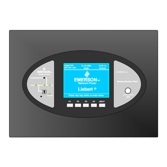
- Page 1 Liebert Remote Monitoring Panel ® User Manual EMERSON ™ Network Power S TATUS ™ Liebert NX 12-16-2009 12:22:14 081 kVA -3x3 Single Normal L ie b e r t EMERSON ™ Remote Monitor Panel Network Power Liebert ® Press any key back to main menu...
-
Page 3: Table Of Contents
Power Supply ........ - Page 4 Figure 1 Remote Monitoring Panel components and functions........2 Figure 2 Remote Monitoring Panel layout constraints .
-
Page 5: Important Safety Instructions Save These Instructions
MPORTANT AFETY NSTRUCTIONS SAVE THESE INSTRUCTIONS This manual contains important safety and operating instructions concerning the installation and operation of the Liebert NX Remote Monitoring Panel (RMP). Read all safety, installation and operat- ing instructions before beginning installation. Adhere to all warnings on the unit and in this manual. Follow all operating and user instructions. -
Page 6: Introduction
NTRODUCTION The Liebert NX Remote Monitoring Panel (RMP) is designed as a remote user interface to monitor Liebert NX Uninterruptible Power Systems. The RMP monochrome liquid crystal display measures 122 x 92mm (4.8 x 3.6 inches). It reports the same data and status and alarm messages that are shown by the LCD on the UPS’s door. -
Page 7: Figure 2 Remote Monitoring Panel Layout Constraints
Length 100m (328ft.) (field-supplied) Introduction Liebert NX 12-16-2009 12:22: 14 081 kVA -3x3 Single Normal EMERSON L ie b e r t ™ Network Power EMERSON ™ Remote Monitor Panel Network Power Liebert ® Press any key back to main menu... -
Page 8: Installation
Preliminary checks Before beginning to install the RMP, verify that the equipment has reached site in its own packaging and in good general condition. Please notify immediately the shipper, Emerson Network Power and your local Liebert representative of any damage. -
Page 9: Mounting The Rmp On Drywall
5. Hang the RMP on the wall by slipping the hooks over the heads of the screws and lowering the RMP slowly until the screws are seated in the slotted portion of the hooks. Figure 5 Mounting hole dimensions Emerson Network P ower Up to 328 ft. (100 m) 14-3/16"... -
Page 10: Electrical Connections
Electrical connections Connect the power and communication cables to the RMP as shown in Figure 6. Figure 6 Power and communication cable routing Extract four screws to remove the cable access cover Attach AC Input cable to labeled connector Attach communi- cation cable to... -
Page 11: Figure 7 Rs-485 Cable Connection To Liebert Nx
Connect the RS-485 communication cable to the Liebert NX as shown in Figure 7. Figure 7 RS-485 cable connection to Liebert NX Connect the other end of the RS-485 signal cable to the X4 slot on the monitor board. The monitor board is inside the UPS front door. -
Page 12: Operation
PERATION Startup and Reset The RMP will start as soon as the power supply is connected. The LCD will illuminate without any data displayed; the LEDs will light up yellow. After 20 seconds, all LEDs will turn off and the LCD will show the opening screen, shown in Figure 8, for 10 seconds. -
Page 13: Figure 10 Ups And Rmp Firmware Are Compatible Screen
Figure 10 UPS and RMP firmware are compatible screen When the Silence On/Off button is pushed, the relevant screen in Figure 11 will be displayed for 5 seconds. NOTE The Silence On/Off button will control only the audible alarm in the Remote Monitoring Panel. -
Page 14: Figure 12 Communication With Ups Failed
Figure 12 Communication with UPS failed If the RMP is functioning properly and the connection with UPS is correct, but the UPS does not sup- port the communication function with RMP, then the RMP will display a the screen shown in Figure 13 to report “Firmware is not Compatible with UPS.”... -
Page 15: Led Mimic Power Flow
LED Mimic Power Flow The LEDs mounted on the mimic flow chart represent the various power paths and current UPS oper- ational status. Table 3 Rectifier indicator Green Rectifier in Normal Operation Flashing Input AC Normal, but rectifier not operating Green Rectifier Failed Rectifier Not operating, Input AC Not Available or out of normal range... -
Page 16: Direct Access Push Buttons-Keys
Direct Access Push Buttons—Keys The NX Remote Monitoring Panel has one direct access push button: Silence ON/OFF. The Silence ON/OFF button is a toggle type buzzer mute; any new fault re-enables the buzzer. LCD Monitor and Menu Keys The menu-driven, 320 x 240 dot graphic LCD monitor displays real time data and, at the same time, stores 512 historical records that can be retrieved for reference and diagnosis. -
Page 17: Figure 15 Menu Tree
The summary menu tree is shown in Figure 15. Refer to Table 12 for a detailed description of each menu item. Figure 15 Menu tree Mains (input) TX Input * L-N voltage (V) L-N voltage (V) L-N current (A) L-L voltage (V) Frequency (Hz) L-L voltage (V) Power factor... -
Page 18: Detailed Description Of Menu Items
Detailed Description of Menu Items The description that follows refers to the graphic LCD monitor window shown on Figure 14. UPS System Window: This fixed-pane window displays current time and date and identifies the UPS, its configuration and its status. Table 11 UPS system window Description... - Page 19 Table 12 Descriptions of RMP menus and data window items (continued) Menu Type Item Type Battery voltage (V) Battery current (A) Battery temperature (°C) Battery Remain Time Min. Battery boost charging Battery float charging Battery disconnected Records (history log) Language (choices for text displayed) User may select any of 12 languages for LCD text.
-
Page 20: Table 13 Rmp Messages
Status and Event Messages Refer to Table 13 for descriptions of events and alarms. Table 13 RMP messages Message Description / Suggested Action (if any) Inverter Comm. Fail Internal RS485 communication failure between monitor and inverter Rectifier Comm. Fail Internal RS485 communication failure between monitor and rectifier The CAN communication between different UPSs within a parallel system fails. - Page 21 Table 13 RMP messages (continued) Message Description / Suggested Action (if any) This alarm is triggered by an inverter software routine when the inverter and bypass waveforms are misaligned by more than 6 degrees in phase. This alarm resets automatically once the condition is no longer true.
- Page 22 Table 13 RMP messages (continued) Message Description / Suggested Action (if any) The phase sequence direction of bypass voltage is reversed. Normally, the phase of phase B lags 120 degrees behind phase A, and the phase of phase C Bypass Phase Reversed lags 120 degrees behind phase B.
- Page 23 Monitor Flash Update Monitor firmware is being update Input contactor fault Input contactor is in fault Contactor P.S. 1 fault Contactor Power Supply board 1 Fault Contactor P.S. 2 fault Contactor Power Supply board 2 Fault LBS abnormal LBS is abnormal DSP firmware error The inverter firmware does not match with the rectifier firmware.
-
Page 24: Prompt (Popup) Windows
Prompt (Popup) Windows The prompt window is displayed during the operation of the system to alert the user to certain condi- tions and / or to require user confirmation of a command. NOTE The items in Table 14 are visible form the RMP, but the controls for them are available only at the UPS. -
Page 25: Default Screen Saver
Figure 16 Help screen 3.10 Default screen saver This default screen is displayed following 2 minutes of operation with no new alarm or activity. After another 2 minutes of inactivity, the backlight turns off. Press any key (F1-F4 or Help) to reactivate the screen. -
Page 26: Technical Specifications
ECHNICAL PECIFICATIONS Table 16 Mechanical specifications Mechanical Characteristics Units Height Width Depth Weight Ventilation Cable entry Color Protection Grade Table 17 Environmental specifications Environmental Characteristics Operating Temperature Relative humidity Acoustical noise Altitude of operation Storage-transport temperature Table 18 Electrical specifications Electrical Characteristics Rated input voltage Input voltage range... -
Page 27: Agency And Certifications
Agency and Certifications Safety Standard: IEC/EN/AS 62040-1-1 incorporating applicable portions of IEC/EN/UL/AS 60950-1 Certification: CE and UL 60950-1:2003, First Edition CSA C22.2 No. 60950-1-03 1st Ed. Electromagnetic Compatibility Standard: IEC/EN/AS 62040-2 incorporating applicable portions of emission and immunity standards as detailed in Tables 20 and 21 below. Table 20 Electromagnetic interference (EMI)—emission limits Standard... - Page 28 Embedded Computing Connectivity Embedded Power DC Power Monitoring Business-Critical Continuity, Emerson Network Power and the Emerson Network Power logo are trademarks and service marks of Emerson Electric Co. ©2008 Emerson Electric Co. Technical Support / Service Liebert.monitoring@emerson.com Outside the US: 614-841-6755 upstech@emersonnetworkpower.com...
Need help?
Do you have a question about the Liebert Remote Monitoring Panel and is the answer not in the manual?
Questions and answers