Table of Contents
Advertisement
Quick Links
SAFETY INFORMATION AND INSTALLATION MANUAL
MODELS EL36L, EL36LD AND VE36LBHB
PLEASE READ THIS MANUAL BEFORE INSTALLING
AND USING APPLIANCE.
WARNING: If the information in this manual is not fol-
lowed exactly, an electrical shock or fire may result caus-
ing property damage, personal injury or loss of life.
— Do not store or use gasoline or other flammable va-
pors and liquids in the vicinity of this or any other
appliance.
— Installation and service must be performed by a
qualified service agency.
This fireplace meets the construction and safety stan-
dards of H.U.D. for application in manufactured homes
when installed according to these instructions.
INSTALLER: Leave this manual with the appliance.
CONSUMER: Retain this manual for future reference.
ELECTRIC FIREPLACE/INSERT
FOR YOUR SAFETY
For more information, visit www.desatech.com
Patent No. 7,219,456 B1
Advertisement
Table of Contents

Related Manuals for Desa EL36L


Summary of Contents for Desa EL36L
- Page 1 ELECTRIC FIREPLACE/INSERT SAFETY INFORMATION AND INSTALLATION MANUAL Patent No. 7,219,456 B1 MODELS EL36L, EL36LD AND VE36LBHB PLEASE READ THIS MANUAL BEFORE INSTALLING AND USING APPLIANCE. WARNING: If the information in this manual is not fol- lowed exactly, an electrical shock or fire may result caus- ing property damage, personal injury or loss of life.
-
Page 2: Table Of Contents
TABLE OF CONTENTS Safety ..............2 Cleaning .............. 9 Listing Approvals ..........3 Servicing .............. 9 Product Dimensions ..........3 Wiring Diagram ..........14 Product Identification ........... 4 Troubleshooting ..........15 Unpacking and Testing ........4 Replacement Parts ..........16 Locating Fireplace .......... -
Page 3: Listing Approvals
SAFETY Continued 14. A heater has hot and arcing or sparking 18. Always disconnect power before perform- parts inside. Do not use it in areas where ing any cleaning, maintenance or reloca- gasoline, paint or flammable liquids or tion of heater. vapors are used or stored. -
Page 4: Product Identification
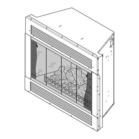
PRODUCT IDENTIFICATION Flame Control Control Remote Hide Ember Control Panel Backlight Door Control Heat Vents (Behind Door) Front Glass Heater Flame Ember Backlight Power Heater Magnetic Control Catch ON/OFF Power Button Log Set Figure 2 - Product Identification UNPACkINg AND TESTINg Carefully remove unit from box. -
Page 5: Installation Clearances
LOCATINg FIREPLACE INSTALLATION Continued INSTALLATION CLEARANCES Minimum clearances to combustible construc- CAUTION: Do not expose the tion are: heater to the elements (such as Top, Back and Sides of Recessed Cabinet 0" Min. rain, etc.) Drywall to Sides of Front Face 0"... -
Page 6: Installation
INSTALLATION Continued WARNING - RISK OF FIRE! WARNING: Control panel Wiring to power source must not door on this heater cannot, in be pinched or against a sharp any way, be covered as it may edge. create a fire hazard. BUILT-IN INSTALLATION WARNING - RISK OF FIRE! Built-in installations require a framed enclo-... -
Page 7: Operation
INSTALLATION Continued A hearth extension is suggested for a more This fireplace should be con- pleasing appearance. The fireplace may be nected to a dedicated 15 amp raised on a wood or non-combustible platform (120/60) or 20 amp (240/60), supporting its entire width and depth and circuit as other appliances may extending in front of the fireplace as long as louvers are not obstructed. -
Page 8: Accessory Installation
OPERATION Continued The heater is pre-set to the following control must remain within 20 feet (6 m) temperatures: of fireplace to be effective. HIGH will shut off when room reaches 4. When power switch is turned off, fireplace approximately 86° F (30° C). settings go back to default (see Figure 10). -
Page 9: Cleaning
ACCESSORY INSTALLATION Continued Removing Bifold Glass Doors 2. Fully fold frame assembly and slide upper Bifold doors may be removed for replacing edge towards center of firebox opening or cleaning. until the guide pins are free of the frame rail (see Figure 11, page 8). 1. - Page 10 SERVICINg Continued REPLACING SCREENS 2. Open bi-fold doors (if equipped) and screens. 1. Open upper control panel door. Turn power switch off. 3. Remove screws securing each side of log to brackets (see Figure 13, page 9). 2. Open bi-fold doors (if equipped). 4.
- Page 11 SERVICINg Continued SCREEN GLASS 7. Reattach wires to motor and LED drum. Note: LED drum wires are polarity sensi- 1. In the event of glass breakage, vacuum all tive and must be connected correctly. remaining glass pieces with a shop vac. DO White wire plugs onto left terminal and red NOT VACUUM WHILE PIECES ARE HOT.
- Page 12 SERVICINg Continued TRANSFORMER Blower 1. Follow steps 1 through 6 under Service Preparation, page 10. 2. Disconnect transformer wires from control board. 3. Remove 2 screws from firebox surround to remove transformer (see Figure 18). 4. Remove and discard transformer. Heater 5.
- Page 13 SERVICINg Continued BACKLIGHT LED STRIP 3. Squeeze top of standoffs to remove board. 1. Follow steps 1 through 4 under Service 4. Gently push new board onto standoffs. Preparation, page 10. 5. Connect wires to remote sensor board. 2. Disconnect wires from backlight LED strip.
-
Page 14: Wiring Diagram
WIRINg DIAgRAM White Yellow Remote Control Sensor (Infrared) Black White LED Backlight Strip LED Ember Strip Black White Cyan YLW YLW Blue Gray www.desatech.com 122663-01D... -
Page 15: Troubleshooting
TROUBLESHOOTINg WARNING: Turn off appliance and let cool before servicing. Only a qualified service person should service and repair heater. OBSERVED PROBLEM POSSIBLE CAUSE REMEDY Fireplace turns off and will 1. Fireplace has overheated 1. Reset switch by turning not turn on and safety device has main power switch off and caused thermal switch to... -
Page 16: Replacement Parts
REPLACEMENT PARTS Note: Use only original replacement parts. Usually, we will ask you to return the part to This will protect your warranty coverage for the factory. parts replaced under warranty. PARTS NOT UNDER WARRANTY PARTS UNDER WARRANTY Contact authorized dealers of this product. If Contact authorized dealers of this product. -
Page 17: Accessories
ACCESSORIES Purchase these accessories from your 36" PERIMETER TRIM KITS local dealer. If they can not supply these PT36 - Black accessories, either contact your nearest PT36B - Brushed Brass Parts Central or call DESA Heating, LLC at PT36PB - Polished Brass 1-866-672-6040 for information. -
Page 18: Parts
PARTS MODEL EL36L, EL36LD, VE36LBHB www.desatech.com 122663-01D... - Page 19 PARTS MODELS EL36L, EL36LD, VE36LBHB This list contains replaceable parts used in your fireplace. When ordering parts, follow the instructions listed under Replacement Parts on page 16 of this manual. PART NO. DESCRIPTION QTY. 120929-01 Door Handles * 120929-02 LED Ember Strip 120929-03 Log Set 120929-04 Rear Glass (Screen) 120929-05 Flame Effect Mirror...
-
Page 20: Warranty
WARRANTY kEEP THIS WARRANTY Model (located on product or identification tag) _____________________________ Serial No. (located on product or identification tag) __________________________ Date Purchased __________________________ Keep receipt for warranty verification. DESA HEATINg, LLC LIMITED WARRANTIES New Products Standard Warranty: DESA Heating, LLC warrants this new product and any parts thereof to be free from defects in material and workmanship for a period of one (1) year from the date of first purchase from an authorized dealer provided the product has been installed, maintained and operated in accordance with DESA Heating, LLC’s warnings and instructions.
Need help?
Do you have a question about the EL36L and is the answer not in the manual?
Questions and answers