Table of Contents
Advertisement
Quick Links
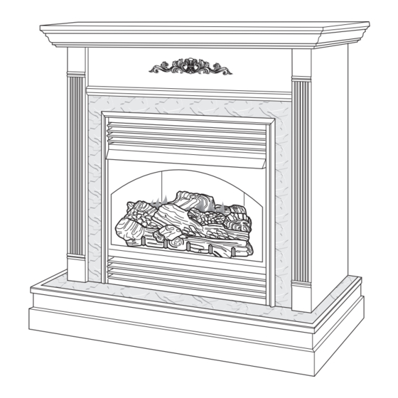
UNVENTED (VENT-FREE) GAS FIREPLACE
OWNER'S OPERATION AND INSTALLATION MANUAL
Shown with optional cabinet mantel, hearth base and trim accessories.
EFS33PRB, EFS33NRB, VSGF33PRB AND VSGF33NRB
REMOTE-READY FIREPLACE SYSTEM
WARNING: If the information in this manual is not fol-
lowed exactly, a fire or explosion may result causing
property damage, personal injury, or loss of life.
— Do not store or use gasoline or other flammable
vapors and liquids in the vicinity of this or any other
appliance.
— WHAT TO DO IF YOU SMELL GAS
•
Do not try to light any appliance.
•
Do not touch any electrical switch; do not use any
phone in your building.
•
Immediately call your gas supplier from a neighbor's
phone. Follow the gas supplier's instructions.
•
If you cannot reach your gas supplier, call the fire
department.
— Installation and service must be performed by a quali-
fied installer, service agency, or the gas supplier.
For more information, visit www.desatech.com
Save this manual for future reference.
Advertisement
Table of Contents

Subscribe to Our Youtube Channel
Related Manuals for Desa EFS33PRB


Summary of Contents for Desa EFS33PRB
- Page 1 UNVENTED (VENT-FREE) GAS FIREPLACE OWNER’S OPERATION AND INSTALLATION MANUAL Shown with optional cabinet mantel, hearth base and trim accessories. EFS33PRB, EFS33NRB, VSGF33PRB AND VSGF33NRB REMOTE-READY FIREPLACE SYSTEM WARNING: If the information in this manual is not fol- lowed exactly, a fire or explosion may result causing property damage, personal injury, or loss of life.
-
Page 2: Table Of Contents
WARNING: Improper installation, adjustment, altera- tion, service, or maintenance can cause injury or prop- erty damage. Refer to this manual for correct installation and operational procedures. For assistance or addi- tional information consult a qualified installer, service agency, or the gas supplier. WARNING: This is an unvented gas-fired heater. -
Page 3: Safety Information
SAFETY INFORMATION WARNING: Do not allow fans to blow directly into the fireplace. WARNING: This product con- tains and/or generates chemicals Avoid any drafts that alter burner known to the State of California flame patterns. Ceiling fans can to cause cancer or birth defects, create drafts that alter burner flame patterns. -
Page 4: Product Identification
SAFETY INFORMATION 12. Do not use fireplace if any part has been exposed to or under water. Immediately call a qualified Continued service technician to inspect the fireplace and to 1. This appliance is only for use with the type of replace any part of the control system and any gas indicated on the rating plate. -
Page 5: Local Codes
LOCAL CODES SAFETY DEVICE This fireplace has a pilot with an Oxygen Depletion Install and use fireplace with care. Follow all local Sensing (ODS) safety shutoff system. The ODS/ codes. In the absence of local codes, use the lat- pilot is a required feature for vent-free room heat- est edition of The National Fuel Gas Code ANSI ers. - Page 6 AIR FOR COMBUSTION Confined and Unconfined Space The National Fuel Gas Code, ANSI Z223.1/ AND VENTILATION NFPA 54 defines a confined space as a space Continued whose volume is less than 50 cubic feet per 1,000 Btu per hour (4.8 m per kw) of the aggregate input While it is good to make your home energy effi- rating of all appliances installed in that space and...
- Page 7 AIR FOR COMBUSTION VENTILATION AIR AND VENTILATION Ventilation Air From Inside Building This fresh air would come from an adjoining un- Continued confined space. When ventilating to an adjoining Example: unconfined space, you must provide two permanent 40,000 Gas water heater ______________ Btu/Hr openings: one within 12"...
-
Page 8: Installation
INSTALLATION Note: Your fireplace is designed to be used in zero clearance installations. Wall or framing material NOTICE: This heater is intended can be placed directly against any exterior surface for use as supplemental heat. on the rear, sides, or top of your fireplace, except where standoff spacers are integrally attached. - Page 9 INSTALLATION Continued ASSEMBLING AND ATTACHING OPTIONAL PERIMETER TRIM (Included with Mantel Accessory) IMPORTANT: If you are recessing the firebox in a wall, do not attach trim at this time. See Built-In Fireplace Installation, page 11. Note: The instructions below show assembling and attaching trim to fireplace.
- Page 10 INSTALLATION 4. Place hearth base accessory against wall at instal- lation location. Cut an access hole in hearth top Continued to run flexible gas line to fireplace (see Figure CONVENTIONAL FIREPLACE 9). Make sure to locate access hole so cabinet INSTALLATION mantel will cover it when installed.
- Page 11 INSTALLATION 3. Install gas piping into fireplace location. This installation includes an approved flexible gas Continued line (if allowed by local codes) after the equip- 11. Carefully insert fireplace into cabinet mantel. ment shutoff valve. The flexible gas line must Be careful not to scratch or damage hearth base, be the last item installed on the gas piping.
- Page 12 INSTALLATION INSTALLING GAS PIPING TO FIREPLACE LOCATION Continued Mantel Clearances for Built-In WARNING: This appliance Installation requires a 1/2" NPT (National If placing mantel above built-in fireplace, you must Pipe Thread) inlet connection to meet minimum clearance between mantel shelf and the pressure regulator.
- Page 13 INSTALLATION Continued For propane/LP units, the installer must supply an external regulator. The external regulator will reduce incoming gas pressure. You must reduce incoming gas pressure to between 11 and 14 inches of water. If you do not reduce incoming gas pres- sure, heater regulator damage could occur.
- Page 14 INSTALLATION Continued CONNECTING FIREPLACE TO GAS SUPPLY Installation Items Needed • 5/16" hex socket wrench or nut-driver • Phillips screwdriver • sealant (resistant to propane/LP gas, not provided) 1. Remove fireplace screen. Remove two screws that hold fireplace screen in place for shipping. These screws are located near top of screen.
- Page 15 INSTALLATION 2. Pressurize supply piping system by either opening propane/LP supply tank valve for Continued propane/LP gas or opening main gas valve CHECKING GAS CONNECTIONS located on or near gas meter for natural gas, or using compressed air. WARNING: Test all gas piping 3.
- Page 16 Notch 7. Turn off fireplace (see To Turn Off Gas to Bars Appliance, page 18). INSTALLING LOGS (MODELS Grate EFS33NRB, EFS33PRB, Prongs VSGF33NRB, AND VSGF33PRB) Figure 24 - Installing Front Log WARNING: Failure to posi- tion the parts in accordance with these diagrams or failure to use only parts specifically...
-
Page 17: Operating Fireplace
OPERATING FIREPLACE NOTICE: During initial operation of new fireplace, burning logs FOR YOUR SAFETY will give off a paper-burning READ BEFORE LIGHTING smell. Open damper or window WARNING: If you do not fol- to vent smell. This will only last low these instructions exactly, a few hours. - Page 18 OPERATING FIREPLACE TO TURN OFF GAS TO APPLIANCE Continued Shutting Off Heater 7. With control knob pressed in, press and 1. Turn control knob clockwise to the release ignitor button. This will light pilot. OFF position. The pilot is attached to the front burner. If 2a.
- Page 19 OPERATING FIREPLACE 3. Press the POWER and LOCK buttons together to turn off the fireplace. Continued Auto (Thermostatic) Mode Flame Adjustment Knob 1. Press the POWER and LOCK buttons together to turn on the hand-held remote control. 2. Press AUTO button to select this mode. 3.
-
Page 20: Inspecting Burners
OPERATING FIREPLACE INSPECTING BURNERS Continued Check pilot flame pattern and burner flame pat- terns often. 2. The receiver continuously receives signals from the hand-held remote to control the PILOT FLAME PATTERN room temperature. If the hand-held remote Figure 34 shows a correct pilot flame pattern. is misplaced, obstructed, or for any reason Figure 35 shows an incorrect pilot flame pattern. -
Page 21: Cleaning And Maintenance
INSPECTING BURNERS WARNING: Failure to keep Continued the primary air opening(s) of the burner(s) clean may result in NOTICE: Do not mistake orange sooting and property damage. flames with yellow tipping. Dirt or other fine particles are burned BURNER INJECTOR HOLDER AND by fireplace, causing brief PILOT AIR INLET HOLE patches of orange flame. -
Page 22: Wiring Diagram
6. In case any large clumps of dust have now been pushed into the burner repeat steps 3 and 4, page 21. Clean the pilot assembly also. A yellow tip on the pilot flame indicates dust and dirt in the pilot as- sembly. -
Page 23: Troubleshooting
TROUBLESHOOTING WARNING: Turn off heater and let cool before servicing. Only a qualified service person should service and repair heater. CAUTION: Never use a wire, needle, or similar object to clean ODS/pilot. This can damage ODS/pilot unit. Note: All troubleshooting items are listed in order of operation. OBSERVED PROBLEM POSSIBLE CAUSE REMEDY... - Page 24 TROUBLESHOOTING Continued OBSERVED PROBLEM POSSIBLE CAUSE REMEDY ODS/pilot lights but flame goes 1. Control knob not fully 1. Press in control knob fully out when control knob is re- pressed in leased 2. Control knob not pressed in 2. After ODS/pilot lights, keep con- long enough trol knob pressed in 30 seconds 3.
- Page 25 TROUBLESHOOTING Continued OBSERVED PROBLEM POSSIBLE CAUSE REMEDY Moisture/condensation noticed 1. Not enough combustion/ven- 1. Refer to Air for Combustion on windows tilation air and Ventilation requirements (page 5) Heater produces a whistling noise 1. Turning control knob to HI po- 1.
- Page 26 TROUBLESHOOTING Continued WARNING: If you smell gas • Shut off gas supply. • Do not try to light any appliance. • Do not touch any electrical switch; do not use any phone in your building. • Immediately call your gas supplier from a neighbor’s phone. Fol- low the gas supplier’s instructions.
-
Page 27: Replacement Parts
1-866-672-6040. When calling please have your • purchase date model and serial numbers of your heater ready. Usually, we will ask you to return the part to the You can also visit DESA Heating Productsʼ techni- factory. cal services web site at www.desatech.com PARTS NOT UNDER WARRANTY Contact authorized dealers of this product. -
Page 28: Illustrated Parts Breakdown And Parts List
ILLUSTRATED PARTS BREAKDOWN LOG BASE ASSEMBLY MODELS EFS33NRB, VSGF33NRB, EFS33PRB AND VSGF33PRB www.desatech.com 113132-01B... - Page 29 PARTS LIST This list contains replaceable parts used in your fireplace. When ordering parts, follow the instructions listed under Replacement Parts on page 27 of this manual. PART NUMBER EFS33NRB EFS33PRB VSGF33NRB VSGF33PRB DESCRIPTION QTY. 110881-04 110881-04 Front Log 110881-05...
- Page 30 ILLUSTRATED PARTS BREAKDOWN FIREPLACE MODELS EFS33NRB, VSGF33NRB, EFS33PRB AND VSGF33PRB www.desatech.com 113132-01B...
- Page 31 PARTS LIST FIREPLACE MODELS EFS33NRB, VSGF33NRB, EFS33PRB AND VSGF33PRB This list contains replaceable parts used in your fireplace. When ordering parts, follow the instructions listed under Replacement Parts on page 27 of this manual. PART NUMBER DESCRIPTION QTY. 101357-01 Top Outer Casing...
-
Page 32: Accessories
G3009U Series - Unfinished cal dealer. If they can not supply these accessories, G3010F Series - Oak Finished call DESA Heating Products at 1-866-672-6040 For all models. The corner hearth base is designed for information. You can also write to the address for use with the corner mantels to create a hand- listed on the back page of this manual. - Page 33 ACCESSORIES Continued Mantel Hearth Base Trim Trim CABINET MANTEL AND FULL HEARTH BASE LAMINATE TRIM FOR HEARTH OR GMC90F Series - Oak Finished GMC91U Series - Unfinished Birch MANTEL GMC92F Series - Cherry Finished Birch G3002J Series - Jade Marble Laminate For all models.
- Page 34 ACCESSORIES WALL-MOUNT THERMOSTAT SWITCH - GWMT1 (Not Shown) Continued For all models. The desired comfort setting can be selected on the wall thermostat and the fireplace will automatically cycle from pilot to the heat setting selected. WALL-MOUNT ON/OFF SWITCH - GWMS2 (Not Shown) For all models.
- Page 35 NOTES _____________________________________________________ ______________________________________________________ ______________________________________________________ ______________________________________________________ ______________________________________________________ ______________________________________________________ ______________________________________________________ ______________________________________________________ ______________________________________________________ ______________________________________________________ ______________________________________________________ ______________________________________________________ ______________________________________________________ _____________________________________________________ ______________________________________________________ ______________________________________________________ ______________________________________________________ ______________________________________________________ ______________________________________________________ ______________________________________________________ ______________________________________________________ ______________________________________________________ ______________________________________________________ ______________________________________________________ ______________________________________________________ ______________________________________________________ _____________________________________________________ ______________________________________________________ ______________________________________________________ ______________________________________________________ ______________________________________________________ ______________________________________________________ ______________________________________________________ ______________________________________________________ ______________________________________________________ 113132-01B www.desatech.com...
-
Page 36: Warranty Information
This warranty is extended only to the original retail purchaser. This warranty covers the cost of part(s) required to restore this heater to proper operating condition and an allowance for labor when provided by a DESA Heating Products Authorized Service Center. Warranty part(s) MUST be obtained through authorized dealers of this product and/or DESA Heating Products who will provide original factory replacement parts.
Need help?
Do you have a question about the EFS33PRB and is the answer not in the manual?
Questions and answers