Advertisement
INSTRUCTIONSHEETNO.
INSTALLATION
PROCEDURE
FOR
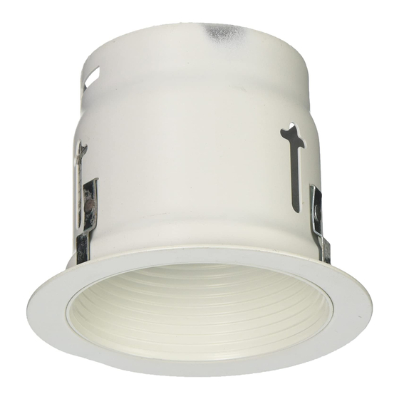
LOW VOLTAGE
REFLECTOR
TRIM
IN THE 1000LV
FRAME-IN
KIT
lS:1052LV
0s90
Page 1 of 2
EAD
AND UNDERSTAND
THESE
INSTRUCTIONS
BEFORE
INSTALLING
FIXTURE.
his fixture
is intsndsd
for installation
in accordance
with the National
Electrical
Code or Iocsl regulations.
3
assure full compliance
with local codes and regulations,
check with your local electrical
inepector
before
wtallation.
To prevent electrical
shock, turn off electricity
at fuse box before proceeding.
ietain these Instruction
for maintenance
referenc~
?~%~
FIG. B
FIG. C
FIG. D
1. FRAME-IN
2. CLOSE4N
3, eNAP-ON
4. PuSH-UP
WARNING:
BEFORE INSTALLING REFLEClOR
TIRM TO FRAME4N KIT, READ MARKINGS
IN REFLEClOR
TRIM AND fN SOCK~
CUP OF FRAME4N KIT TO DEf'ERMINE
LAMP WAITAGE AND TYPE APPLICABLE
FOR
YOUR lNSTALLATfON. IF IC. TYPE FRAME.fN KIT IS USED, IT MAY BE INSTALLED fN DIRECT CONTACT WITH
INSULATED CEILING. IF A NON IC. TYPE FRAME4N
KIT IS USED, DO No
INSTALL lNSULATfON WITHIN
3 INCHSS OF FIXWRE
SIDES OR WIRING .COMPARTMENT,
NOR ABOVE FfXTURE IN SUCH A MANNER AS ~
ENTRAP HEAT.
1. FRAME-IN (Fig. A)
4
r-.
See Frame-In Kit Instruction
Sheet for installation
procedwe.
,–
FRAMINGKIT
MOUNTSFLUSH
!.;
!.
R~ATE
RUIO-CLIPS
(Fig. B)
,.,'
ON CEILINGMATERIAL
0"
\
As shown
in Fig. E.
... $1...-
.. .. . . . . . ..
: ,,..,. ,, ::.:,.;.
L
SNARON
(Fig. C).
Disconnect
SOCKET from FRAME-IN
KIT WIRES
CEILING
-.: .".~ .-:.
MATERIAL
by pulling
off the insulated
FEMALE
R~-CLIP
" ":-~~<
;
CONNECTORS.
Insert FRAME-IN
KIT WIRES with
POSITION
,.,
,.
FEMALE
CONNECTORS
through
%" dia HOLE
on top of REFLECTOR TRIM. Reconnect
SOCKET
FIG. E
(provided
with REFLECTOR TRIM) by pushing
MALE CONNECTORS
into FEMALE CONNECTORS
– SOCKET GUp
(Fig. G.)
*
LANCING
Engage TAB from SOCKET CUP into one of the
. . .
SLOTS on top of REFLECTOR TRIM and push
i" HOLE
,*
.
other end of SOCKET CUP with LANCING
into
,=
TAe
the other
SLOT (Fig. F).
SLOTS
,}
REFLECTOR T RIM
4.
PUSH-UP (Fig. D).
Push REFLECTCR TRIM into ceiling
until flange
FIG. F
SOCKET
is flush to ceiling
(Fig. D).
INSULATING S LEEVING
MALECONNECTORS
[Altached to Sooket w ires)
SEE BACK PAGE FOR LAMPING
INSTALLATION
AND ADJUSTMENT.
FEMALE GONN ECTORS
(Attached to FixtureWires)
FIG. G
D-9
C31"ITC>I-I
Is
1?
:V:::::;,N:;::::,E:;
:Y::
Advertisement
Table of Contents

Related Manuals for Lightolier REFLECTOR TRIM


Summary of Contents for Lightolier REFLECTOR TRIM
- Page 1 INSTRUCTIONSHEETNO. LOW VOLTAGE lS:1052LV INSTALLATION PROCEDURE REFLECTOR TRIM IN THE 1000LV FRAME-IN Page 1 of 2 0s90 AND UNDERSTAND THESE INSTRUCTIONS BEFORE INSTALLING FIXTURE. his fixture is intsndsd for installation in accordance with the National Electrical Code or Iocsl regulations. assure full compliance with local codes and regulations, check with your local electrical...
- Page 2 (attached to socket leads) from female connectors (attached to fixture leads) and replacing with a new eocket procured through Lightolier (Fig. G). A, Check to see that power is OFF before Iamping relamping. PINHOLE PLATE FACE B. Remove PINHOLE...
Need help?
Do you have a question about the REFLECTOR TRIM and is the answer not in the manual?
Questions and answers