Hitachi L100 Series Quick Reference Manual
Hide thumbs
Also See for L100 Series:
- Instruction manual (193 pages) ,
- Service manual (69 pages) ,
- User manual (13 pages)

Related Manuals for Hitachi L100 Series


Summary of Contents for Hitachi L100 Series
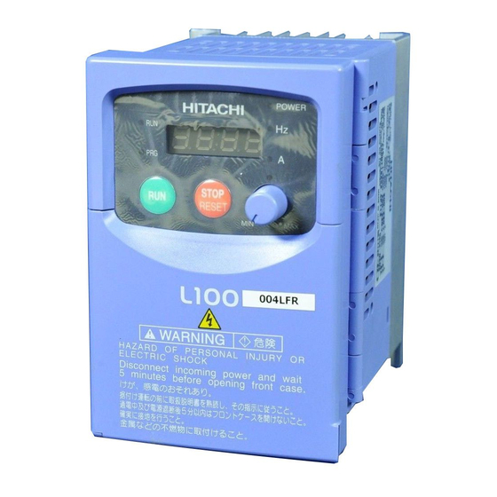
- Page 1 HITACHI L100 Series Inverter Quick Reference Guide • Single-phase Input 200V Class • Three-phase Input 200V Class • Three-phase Input 400V Class Hitachi Industrial Equipment Systems Co., Ltd. Manual No. NB5412XD • Dec. 2003...
-
Page 2: Power Circuit Terminals
Caution: Be sure to read the L100 Inverter Manual and follow its Cautions and Warnings for the initial product installation. This Quick Reference Guide is intended for reference use by experienced users in servicing existing installations. Power Circuit Terminals –002NFE/NFU, –004NFE/NFU, –005NFE Jumper –... -
Page 3: Control Circuit Terminals
Control Circuit Terminals Logic 5 4 3 2 1 inputs H O OI CM2 12 11 AL0 AL1 AL2 Analog Logic Alarm Analog inputs outputs relay outputs Terminal Description Ratings and Notes Name +24V for logic inputs 24VDC supply, 30 mA max. (Notes: Do not use for network power Do not short to terminal L) - Page 4 Terminal Description Ratings and Notes Name Analog input, voltage 0 to 9.6 VDC range, 10VDC nominal, 12VDC max., input impedance 10 kΩ +10V analog reference 10VDC nominal, 10 mA max. Relay common contact Contact rating Max resistive load = 250VAC, Relay contact, 2.5A;...
-
Page 5: Basic Wiring Diagram
Basic Wiring Diagram The following wiring diagram shows the power and motor connec- tions for basic operation. The optional signal input wiring supports external Fwd and Rev Run command, and a speed potentiometer. L100 From 3-phase power input (T1) (L1) source (See specifications Motor... -
Page 6: Inverter Keypad Operation
Inverter Keypad Operation Run Key Enable LED Parameter Display Run/Stop LED Program/Monitor LED Power LED POWER Display Units LEDs HITACHI Hertz 5 0.0 Amperes STOP Potentiometer RESET Enable LED Potentiometer FUNC. Stop/Reset Key Run Key Up/Down Keys Store Key Function Key •... - Page 7 • Potentiometer – Allows an operator to directly set the motor speed when the potentiometer is enabled for output frequency control. • Potentiometer Enable LED – ON when the potentiometer is enabled for value entry. • Parameter Display – A 4-digit, 7-segment display for parame- ters and function codes.
- Page 8 Keypad Navigation Map Monitor Mode Program Mode Display data Select Parameter Edit Parameter powerdown Store as powerup FUNC. default c 9 1 Increment/ decrement c 0 1 value C – – Edit FUNC. 1 2 3.4 FUNC. – – FUNC. A –...
-
Page 9: Powerup Test
Powerup Test The Powerup Test procedure uses minimal parameter settings to run the motor. The procedure describes two alternative methods for commanding the inverter: via the inverter keypad, or via the logic terminals. • Check power input and motor output wiring (see page 4 diagram). •... -
Page 10: Error Codes
Error Codes The L100 series inverters will trip on over-current, over-voltage, and under-voltage to protect the inverter. The motor output turns OFF, allowing the motor to free-run to a stop. Press the Stop/Reset key to reset the inverter and clear the error. Basic Error Codes Error Name... - Page 11 Error Name Probable Cause(s) Code Thermistor • Thermistor input, [THM] and [L], is over the temp. threshold Under-voltage (brown- • Low input voltage caused the out) with output shutoff inverter to turn OFF the motor output and try to restart. If unsuccessful, a trip occurs.
-
Page 12: Restoring Factory Default Settings
Restoring Factory Default Settings Action Display Function/Parameter “B” Group selected FUNC. Press needed. First “B” Group parame- FUNC. Press Country code for Press/hold until... initialization selected 00 = Japan FUNC. Press . If setting is 01 = Europe 02 = United States correct, then skip next step. -
Page 13: Parameter Tables
Note: After initializing the inverter, use the Powerup Test on page 8 to get the motor running again. Parameter Tables “D” Group: Monitoring Functions Func. Name / Description Units Code D_01 Output frequency monitor D_02 Output current monitor D_03 Rotation direction monitor —... - Page 14 Trip History Navigation Map No error Monitor Mode Error _ _ _ _ exists? Display data o.0 0 E 0 7 Error code FUNC. FUNC. 6 0.0 Output frequency at trip point FUNC. Motor current 4.0 0 at trip point FUNC.
-
Page 15: "F" Group: Main Profile Parameters
Parameter tables for user-settable functions follow these conven- tions: • Some parameters specify an option code. Where applicable, the options codes will be in a bulleted list in the Name/Description column. • The default values apply to all models unless otherwise noted for each parameter... -
Page 16: "A" Group: Standard Functions
“A” Group: Standard Functions Default Func. Value Name / Description Code –FE / –FU / Value –FR A_01 Frequency source setting 01 / 01 / 00 • 00 Keypad potentiometer • 01 Control terminal • 02 Function F_01 setting A_02 Run command source setting 01 / 01 / 02 •... - Page 17 Default Func. Value Name / Description Code –FE / –FU / Value –FR A_41 Torque boost method selection • 00 Manual torque boost • 01 Automatic torque boost A_42 Manual torque boost value A_43 Manual torque boost frequency adjust- 10.0 ment A_44 V/f characteristic curve selection...
-
Page 18: "B" Group: Fine-Tuning Functions
Default Func. Value Name / Description Code –FE / –FU / Value –FR A_82 AVR voltage select 230/230/200 400/460/400 A_92 Acceleration (2) time setting 15.0 A_93 Deceleration (2) time setting 15.0 A_94 Select method to switch to Acc2/Dec2 profile • 00 2CH input from terminal •... - Page 19 Default Func. Value Name / Description Code –FE / –FU / Value –FR B_12 Level of electronic thermal setting Rated current of each inverter B_13 Electronic thermal characteristic 01 / 01 / 00 • 00 Reduced torque • 01 Const. torque B_21 Overload restriction operation mode •...
-
Page 20: "C" Group: Intelligent Terminal Functions
Default Func. Value Name / Description Code –FE / –FU / Value –FR B_88 Restart mode after FRS • 00 Restart from 0Hz • 01 Restart from frequency detected from actual speed of motor B_89 Data select for digital operator OPE-J •... - Page 21 Default Func. Value Name / Description Code –FE / –FU / Value –FR C_21 Terminal [11] function Six option codes available C_22 Terminal [12] function (see page 22) C_23 [FM] signal selection Three option codes available (see page 22) C_31 Terminal [11] active •...
- Page 22 Intelligent Input Terminal Listing Symbol Code Input Terminal Name Forward Run/Stop Reverse Run/Stop Multi-speed select, Bit 0 (LSB) Multi-speed select, Bit 1 Multi-speed select, Bit 2 Multi-speed select, Bit 3 (LSB) Jogging 2-stage accel and decel Free-run stop External trip Unattended start protection Software lock Analog input voltage/current sel.
-
Page 23: Analog Input Configuration
Intelligent Output Terminal Listing Symbol Code Input Terminal Name Run signal Freq. arrival type 1 – constant speed Freq. arrival type 2 – over-frequency Overload advance notice signal Output deviation for PID control Alarm signal Analog Input Configuration The following tables show the parameter settings required for vari- ous analog input signal types. - Page 24 Notes:...
Need help?
Do you have a question about the L100 Series and is the answer not in the manual?
Questions and answers