Hitachi L100 SERIES Service Manual
L100 series
Hide thumbs
Also See for L100 SERIES:
- Instruction manual (193 pages) ,
- Quick reference manual (25 pages) ,
- User manual (13 pages)
Table of Contents
Advertisement
Quick Links
L100 SERIES
SERVICE MANUAL
(ADJUSTMENT AND MAINTENANCE)
Model:
European Version
L100-002NFE to L100-022NFE
L100-004HFE to L100-075HFE
US Version
L100-002NFU to L100-022NFU
L100-004HFU to L100-075HFU
L100-037LFU
L100-002MFU to L100-007MFU
Japanese Version
L100-002LFR to L100-037LFR
L100-004HFR to L100-075HFR
L100-002MFR to L100-007MFR
After reading this manual, keep it at hand for future reference
Hitachi, Ltd.
HITACHI INVERTER
Tokyo Japan
NBS541X
Advertisement
Table of Contents

Related Manuals for Hitachi L100 SERIES


Summary of Contents for Hitachi L100 SERIES
- Page 1 HITACHI INVERTER L100 SERIES SERVICE MANUAL (ADJUSTMENT AND MAINTENANCE) Model: European Version L100-002NFE to L100-022NFE L100-004HFE to L100-075HFE US Version L100-002NFU to L100-022NFU L100-004HFU to L100-075HFU L100-037LFU L100-002MFU to L100-007MFU Japanese Version L100-002LFR to L100-037LFR L100-004HFR to L100-075HFR L100-002MFR to L100-007MFR...
-
Page 2: Table Of Contents
INDEX 1. Pre-operation Check 1-1. Check inverter model and Manufacturing number 1-2. Check inverter parameter and motor specification 2. Measurement of The Internal Voltage Supply 3. Trouble Shoot 3-1. Error messages - Possible Cause and Remedy 3-2. Analysis of Various Operating Problems That Do Not Trigger an Trip Message 3-3. - Page 3 Revisions Revision history table Revision contents Date of issue Manual No.
-
Page 4: Pre-Operation Check
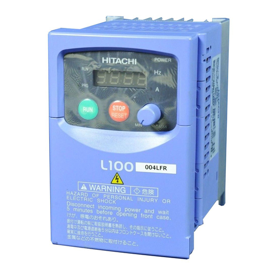
200-240V 7.1 A MFG No. 78H T1129670060 Date: 9708 Hitachi, Ltd. NE16452-6 MADE IN JAPAN You can find these information from the specification label which attached at the side cover of the unit. (1) Description of the model name. L100... -
Page 5: Check Inverter Parameter And Motor Specification
1.2 Check Inverter parameter and motor specification. [1] Inverter specifications. (1) Inverter specifications (Monitor mode) Display Function name Category Screen display Initial Remarks order Code display Output frequency monitor Monitor Output current monitor Monitor Running direction monitor Monitor Feedback data of PID Monitor control monitor Intelligent input terminal... - Page 6 (3) Inverter specifications (Extended function mode : A group) Display Function name Category Screen display Initial Remarks order Code display Frequency destination Running command destination Base frequency Maximum frequency External frequency setting start External frequency setting External frequency setting start rate External frequency setting end rate External frequency start...
- Page 7 (4) Inverter specifications (Extended function mode : B group) Display Function name Category Screen display Initial Remarks order Code display Selection of restart mode Allowable UV time Retry waiting time Electronic thermal level note note note Rated current of each inverter Electronic thermal characteristics Overload restriction...
- Page 8 (5) Inverter specifications (Extended function mode : C group) Display Function name Category Screen display Initial Remarks order Code display Input terminal 1 assign Input terminal 2 assign Input terminal 3 assign Input terminal 4 assign Input terminal 5 assign Input terminal 1 condition Input terminal 2 condition Input terminal 3 condition...
- Page 9 [2] Motor specifications. Output voltage Output frequency Motor MFG number Motor output Rated current Amps Motor poles Rated voltage Motor rated rpm Rated frequency Starting current Amps [3] Load conditions Equipment name Torque characteristics Acceleration time Required torque Deceleration time Load inertia (J) Variable speed range Hz to...
-
Page 10: Measurement Of The Internal Voltage Supply
2. Measurement of the Internal Voltage Supply There are PV5L, PV24L and NV12L internal DC voltage supplies. These supplies are isolated from the main high voltage portion. And it is not possible to measure DC voltages at the non isolated portion. Please make measurements for above mentioned voltages for the isolated portion. -
Page 11: Trouble Shoot
3. Trouble Shoot 3-1. Error Messages - Possible Cause and Remedy: (1) Overcurrent 1 (E 01, E 02, E 03, E 04) Phenomena: Overcurrent for each condition. E 01 : Overcurrent during constant speed operation. E 02 : Overcurrent during deceleration. E 03 : Overcurrent during acceleration. - Page 12 (2) Overload (E 05) Phenomena: Overload of the inverter. This error can be reset 10 seconds after the E05 came out. Cause: Motor load is heavy. Remedy: Reduce the load and/or increase thermal level and/or use bigger capacity of frequency inverter. Cause: V-Boost value is high.
- Page 13 Cause: Period of instantaneous power failure is longer than the set value [b02], or DC bus voltage go down to its detecting level while instantaneous power failure. Remedy: Get rid of the instantaneous power failure, evaluate the power supply system, set bigger value for [b02].
- Page 14 Cause: Influenced by Electrical Magnetic Interference. Remedy: Keep such noise source away from the frequency inverter. Cause: Ambient temperature is too high. Remedy: Take countermeasure against high ambient temperature. Cause: Component itself is defect. Remedy: Replace ISPM (in case of E 11) or I/O board board (in case of E 12). (7) External Trip (E 12) Phenomena: Trip due to have inputted an external signal to “EXT”...
- Page 15 (10) Over voltage at source (E 15) Phenomena: High voltage at power source line. Frequency inverter cannot protect source overvoltage. If it is too high, frequency inverter will be damaged. Cause: Source voltage is too high. Remedy: Check the source voltage continously. Insert AC reactor at source lines.
-
Page 16: Analysis Of Various Operating Problems That Do Not Trigger An Trip Message
3-2. Analysis of Various Operating Problems That Do Not Trigger an Trip message. Problem Possible cause Remedy The motor does not start Mode of frequency command [A01] Check each mode again and/or Run command [A02] is not proper Incorrect power supply condition Check that the power supply is within its specification Inverter is in trip mode... -
Page 17: How To Initialize The Data (Factory Setting)
3-3. How to Initialize the Data (FACTORY SETTING) 1. Select the mode of initialization data to which you want to initialize by [b85]. Japanese version data -----> Set “00” and store EU version data -----> Set “01” and store US version data ----->... -
Page 18: Error Message Comparison
3-4. Error Message comparison Digital Panel DOP / DRW Contents Over current while constant speed OC. Drive driving Over current while deceleration OC. Decel Over current while acceleration OC. Accel Over current at other condition than Over. C above(such as 0Hz,injection brake) Over load Over. -
Page 19: Other Displays
3-5. Other Displays Digital Panel Contents - Reset terminal is ON - During initialization (such as at power-on) - Voltage is within UV level - Power OFF - During retry mode - During initialization as EU settings - During initialization as US settings - During initialization as Japanese settings - Erasing trip histories - Copying with DRW,DRW-2... -
Page 20: Ambient Condition Of The Frequency Inverter (Temperature, Altitude)
4. Ambient Condition of the Frequency Inverter 4-1. Required Derating in case of 50deg, 55deg of Ambient Temperature Inverter ratings can be influenced by many factors. You can find in this section, the relation between ambient temperature and output current (%) and carrier frequency. Standard ratings in 40 degree C Top cover removed condition in 50 degree C max. - Page 21 L100-037LF(U) L100-022NFE(U) 100% 100% Carrier frequency [kHz] Carrier frequency [kHz] L100-007HFE(U) L100-004HFE(U) 100% 100% Carrier frequency [kHz] Carrier frequency [kHz] L100-022HFE(U) L100-015HFE(U) 100% 100% Carrier frequency [kHz] Carrier frequency [kHz]...
- Page 22 L100-055LFU L100-075LFU 100% 100% Carrier frequency [kHz] Carrier frequency [kHz] L100-055HFE(U) L100-075HFE(U) 100% 100% Carrier frequency [kHz] Carrier frequency [kHz] L100-002MFU L100-004MFU L100-007MFU 100% 100% Carrier frequency [kHz] Carrier frequency [kHz]...
-
Page 23: Required Derating Toward Altitude
4-2. Required derating toward altitude 100% 1000 2000 3000 4000 Altitude [m] Example of calculation L100-007NFE (4 Amps) is installed at 2000m of altitude and 16kHz of carrier frequency. Required derating of output frequency of this case will be as follows. 4 [Amps] * 90% * 95% = 3.4 [Amps] Carrier frequency derating Altitude frequency derating... -
Page 24: Level Of Each Detection
5. Level of Each Detection 5-1. DC Bus Voltage Detection Characteristics Frequency inverter has several detection characteristics for DC bus voltage as followings. [1] 200V class DC bus voltage [Vdc] Over voltage level 395V +- 20V Actual DC bus voltage Under voltage recovering level 220V +- 10V... - Page 25 [2] 400V class DC bus voltage [Vdc] Over voltage level 790V +- 40V Actual DC bus voltage Under voltage recovering level 440V +- 20V Under voltage level 380V +- 20V Trip Trip Trip Reset Display Over During Under example of voltage Under voltage...
-
Page 26: Output Current Detection Characteristics
5-2. Output Current Detection Characteristics Frequency inverter has several detection characteristics for output current to protect IGBT from break down, or to protect motor from over heat. [1] Over current Frequency inverter shuts off the output instantaneously when output current exceeds to 200% of its rated current. -
Page 27: Motor Temperature Detection (Ptc)
5-3. Motor Temperature Detection (PTC) Frequency inverter has a motor temperature sensor input (PTC input : PTC resistor). When the resistance value is more than 3k ohm +-10%, the frequency inverter trips with “E35”. Motor L100 inverter PTC thermistor 5(PTC) Except Japanese version 5-4. -
Page 28: Measurement & Replacement Of Subassemblies
6. Measurement & Replacement of Subassemblies 6-1. Insulation Measurement For L100 inverter, do not perform insulation measurements , otherwise MOV will be damaged. (MOV; between R(L1)-G, S(L2)-G, T(L3)-G) 6.2. Power Components Measurements. When checking the power components, the following procedure is recommended: Clear voltage Wait for capacitors discharge Check capacitors for neutrality... - Page 29 [3] Rectifier Measurement (Ll) (L2) (L3) Main circuit of L100 This is to measure 3 rectifiers located lower arm of the input side. Resistance Measurement Allowable Value From R(Ll) S(L2) 50kohm or more S(L2) R(Ll) S(L2) T(L3) T(L3) S(L2) R(L1) T(L3) R(Ll) S(L2)
- Page 30 [4] IGBT Measurement Resistance Measurement Allowable Value From 50kohm or more 50 ohm or less 50 ohm or less DC current detecting resistor (shunt resistor) 50kohm or more (Order of mili ohm) If the result is out of its spec, replace the unit. Please note that this cannot cover 100% to find IGBT failure because if the power devices in failure, sometimes you can find the failure in components while they are activated.
-
Page 31: Maintenance And Inspection Procedure
7. Maintenance and Inspection Procedure 7-1. Precautions (1) Maintenance and Inspection Precautions Be sure to check the followings before starting maintenance and inspection because there is a danger of electrical shock. Display on the digital operation panel and POWER indication has been turned OFF. The voltage between + and - is 15Vdc or lower. - Page 32 When there is no motor connected to the inverter, please use additional resistor like Fig. 7-2. There will be a voltage at output terminal even the frequency command is naught due to the leakage current of the semiconductor devices. Frequency Inverter 220kohm Fundamental wave...
- Page 33 Table 7-1 Measuring Instruments Item Instruments Type of Instrument Remarks Supply voltage and E Moving iron type voltmeter or Fundamental wave L1-L2 L2-L3 L3-L1 effective value Rectifier type voltmeter Supply current and I Moving iron type ammeter Total effective value Supply power and W Electrodynamics wattmeter...
-
Page 34: Maintenance Of Parts
7-3. Maintenance of Parts (1) Maintenance of printed circuit board (I/O board) Printed circuit boards are maintenance free under normal applications except ALARAM relay (hardware). However, in case which maintenance and inspection are necessary, pay attention to the prevention of damage caused by static electricity as shown below. * Prevent damage caused by static electricity MCU and LSI on the printed circuit board can be destroyed by static electricity. -
Page 35: Daily Inspection And Periodical Inspection
8. Daily Inspection and Periodical Inspection Inspection Item Contents Cycle Method Criteria Standard Instruments point replacement daily periodic period Overall Ambient Check ambient temperature, Ambient temperature Thermometer Environment humidity, dust, corrosive gas, oil mist, : -10deg to 40deg, etc. no icing Devices overall Check for abnormal vibrations and Visual and aural... - Page 36 Inspection Item Contents Cycle Method Criteria Standard Instruments point replacement daily periodic period Control circuit Operation check Check the balance of the output Measure the Within 2% of voltage next voltage of each phase to phase output voltage difference between each page without motor.
-
Page 37: Image Block Diagram
R(L1) S(L2) U(T1) T(L3) V(T2) W(T3) CONVERTER I/O BLOCK POWER SUPPLY (I/O board) OPERATION PANEL WITH POTENTIOMETER HITACHI DETECT V,I DRIVE CIRCUIT SERIAL COMMUNICATION COMMUNICATION ISORATION PORT TERMINALS EEPROM USER INTERFACE REMORT OPERATOR EMC DIRECTIVE COMPLIANT WITH DEDICATED NOISE FILTER(OPTION) - Page 38 R(L1) U(T1) S(L2) T(L3) V(T2) W(T3) CONVERTER I/O BLOCK POWER SUPPLY (I/O board) OPERATION PANEL WITH POTENTIOMETER HITACHI DETECT V,I DRIVE CIRCUIT SERIAL COMMUNICATION ISORATION COMMUNICATION PORT TERMINALS EEPROM USER INTERFACE REMORT OPERATOR EMC DIRECTIVE COMPLIANT WITH DEDICATED NOISE FILTER(OPTION)
- Page 39 N(-) P(+) (ISPM) INVERTER CONVERTER R(L1) U(T1) V(T2) T(L3) W(T3) I/O BLOCK POWER SUPPLY (I/O board) OPERATION PANEL WITH POTENTIOMETER HITACHI POWER DETECT V,I STOP RESET DRIVE CIRCUIT FUNC. SERIAL COMMUNICATION COMMUNICATION ISORATION PORT TERMINALS EEPROM USER INTERFACE REMORT OPERATOR...
-
Page 41: Spare Parts List
10-1. Spare Parts list Class Parts Code DWG.No. Parts Name Remarks Quantity 254819 2T004353 2 Key PAD (HITACHI) For all models 254821 2T004372 1 Front case (S) L100-002,004NFE;NFU L100-005--022NFE;NFU 254818 1T001784 1 Front case (L) L100-037--075LFU L100-004--075HFE;HFU L100-002--007MFU 254869 3T015677 1... - Page 42 Parts Code DWG.No. Parts Name Remarks Quantity Class L100-015,055,075HFE;HFU 254270 3T012518 2 Cooling fan L100-015,055LFU 254270 3T012518 2 Cooling fan L100-075LFU L100-022NFE;NFU 254822 3T011924 4 Cooling fan L100-037LFU L100-022--040HFE;HFU L100-002--022NFE;NFU 254827 4T013337 1 ISPM-IO Cable (S) L100-004--040HFE;HFU L100-037LFU 4T013337 4 ISPM-IO Cable (L) L100-055,075LFU;HFE;HFU 3T015514 3...
- Page 43 Parts Code DWG.No. Parts Name Remarks Quantity Class 4T013438 1 Copper bar L100-002,004NFE;NFU 4T013439 1 Copper bar L100-005--022NFE L100-007--022NFU L100-037LFU L100-004--040HFE;HFU L100-002--007MFU L100EUL I/O board L100-002--022NFE;NFU L100-037LFU L100-004--040HFE;HFU L100-002--007MFU L100 075EUL I/O board L100-055,075LFU L100-055,075HFE;HFU CB470 Capacitor board L100-011,015NFE L100-015NFU L100-037LFU CB680 Capacitor board...
- Page 44 Parts Code DWG.No. Parts Name Remark Quantity Class CB470B2T PCB2 L100-011,015NFE L100-015NFU L100-037LFU CB680B2T PCB2 L100-022NFE;NFU L100SB055L PCB2 L100-055LFU L100SB075L PCB2 L100-075LFU CB180B4 PCB2 L100-004HFE;HFU CB270B4 PCB2 L100-007HFE;HFU CB470B4 PCB2 L100-015HFE;HFU CB680B4 PCB2 L100-022HFE;HFU CB470B4 PCB2 L100-030,040HFE L100-040HFU L100SB055H PCB2 L100-055HFE;HFU L100SB075H PCB2...
- Page 45 Parts name Quantity Keypad Front case (L) Key cover Volume knob Top cover (S) Case (S) Rear cover (S) ISPM – IO cable (S) ISPM I/O board PCB2 L100-002NFE 002NFU 004NFE 004NFU...
- Page 46 Parts name Quantity Keypad Front case (L) Key cover Volume knob Top cover (L) Case (M) Rear cover (L) ISPM – IO cable (L) ISPM I/O board PCB2 L100-004HFE 004HFU 005NFE 007NFE 007NFU...
- Page 47 Parts name Quantity Keypad Front case (L) Key cover Volume knob Top cover (L) Case (M) Rear cover (L) ISPM – IO cable (L) ISPM I/O board PCB2 L100-007HFE 007HFU...
- Page 48 Parts name Quantity Keypad Front case (L) Key cover Volume knob Top cover (L) Case (M) Rear cover (L) Cooling fan (L) ISPM – IO cable (L) ISPM I/O board PCB2 L100-015HFE 015HFU...
- Page 49 Parts name Quantity Keypad Front case (L) Key cover Volume knob Top cover (L) Case (L) Rear cover (L) Condensor cover ISPM – IO cable (L) ISPM I/O board Capacitor board PCB2 L100-011NFE 015NFE 015NFU...
- Page 50 Parts name Quantity Keypad Front case (L) Key cover Volume knob Top cover (L) Case (L) Rear cover (L) Condensor cover Cooling fan (L) ISPM – IO cable (L) ISPM I/O board Capacitor board PCB2 L100-022NFE 022NFU 030HFE 037LFU 040HFE 040HFU...
- Page 51 Parts name Quantity Keypad Front case (L) Key cover Volume knob Top cover (L) Case (L) Rear cover (L) Condensor cover Cooling fan (L) ISPM – IO cable (L) ISPM I/O board PCB2 L100-022HFE 022HFU...
- Page 52 Parts name Quantity Keypad Front case (L) Key cover Volume knob Top cover (LL) Case (LL) Rear cover (LL) Condensor cover (LL) Cooling fan (S) ISPM – IO cable (L) ISPM I/O board Capacitor board PCB2 L100-055LFU 055HFU 075HFU 055HFE 075HFE...
- Page 53 Parts name Quantity Keypad Front case (L) Key cover Volume knob Top cover (LL) Case (LL) Rear cover (LL) Condensor cover (LL) Cooling fan (S) ISPM – IO cable (L) ISPM I/O board Capacitor board PCB2 L100-075LFU...
- Page 54 Parts name Quantity Keypad Front case (L) Key cover Volume knob Case (M) Rear cover (L) ISPM – IO cable (L) ISPM I/O board PCB2 L100-002MFU 004MFU...
- Page 55 Parts name Quantity Keypad Front case (L) Key cover Volume knob Case (L) Rear cover (L) Condensor cover ISPM – IO cable (L) ISPM I/O board Capacitor board PCB2 L100-007MFU...
-
Page 56: I/O Board Compatibility
10-2. I/O board compatibility L100 series V: available - : not available NOTE:B32 function is available from “L” or after . NOTE: The “A” is not available from the others revision. NOTE: ”F” is available from L100EULH L100EUL "G","J","K","M","P" board Name “R evision ”... -
Page 57: O,Oi Terminal Adjustment Procedure
10-3. O,OI terminal adjustment procedure If you need fine adjustment with out F31 IN EX%S, IN EX%E function(DOP/DRW), or A group A13,A14 function (on standard panel), please refer to following procedure. Meaning set C91 "01" ; Debug on set C94 "F947" ;... -
Page 58: Kw Setup Procedure
10-4. kW setup procedure To set up kW, we advise you not to use DOP/DRW ! Meaning set C91 "01" ; Debug on set C94 "FAB0" ; kW adress set C95 "xx" ; kW code set B84 "01" ; to excecute FACTORY SETTING Try FACTORY SETTING Check B12' display (F-23 E-THM LVL) B12's display table... - Page 69 End of page...
Need help?
Do you have a question about the L100 SERIES and is the answer not in the manual?
Questions and answers