Epson Stylus Pro Service Manual
Color inkjet printer
Hide thumbs
Also See for Stylus Pro:
- Enlarge copying manual (2 pages) ,
- Specification sheet (1 page) ,
- Service manual (519 pages)
Table of Contents
Advertisement
Quick Links
Advertisement
Chapters
Table of Contents
Troubleshooting

Related Manuals for Epson Stylus Pro


Summary of Contents for Epson Stylus Pro
-
Page 1: Service Manual
EPSON COLOR INKJET PRINTER Stylus Pro SERVICE MANUAL EPSON 4004825... - Page 2 All efforts have been made to ensure the accuracy of the contents of this manual. However, should any errors be detected, SEIKO EPSON would greatly appreciate being informed of them. The above notwithstanding SEIKO EPSON can assume no responsibility for any errors in this manual or the consequence thereof.
- Page 3 POWER SUPPLY CABLE MUST BE CONNECTED, USE EXTREME CAUTION IN WORKING ON POWER SUPPLY AND OTHER ELECTRONIC COMPONENTS. WARNING REPAIRS ON EPSON PRODUCT SHOULD BE PERFORMED ONLY BY AN EPSON CERTI- FIED REPAIR TECHNICIAN. MAKE CERTAIN THAT THE SOURCE VOLTAGE IS THE SAME AS THE RATED VOLTAGE, LISTED ON THE SERIAL NUMBER/RATING PLATE.
- Page 4 Includes a step-by-step guide for product disassembly and assembly. CHAPTER 4. ADJUSTMENTS Includes a step-by-step guide for adjustment. CHAPTER 5. TROUBLESHOOTING Provides Epson-approved techniques for adjustment. CHAPTER 6. MAINTENANCE Describes preventive maintenance techniques and lists lubricants and adhesives required to service the equipment. APPENDIX Describes connector pin assignments, circuit diagrams, circuit board component layout and exploded diagram.
- Page 5 REVISION SHEET Revision Issue Date Revision Page Rev. A May 30, 1995 1st issue 1 - 2, 4-7 Rev. B June 5, 1995 Change Fig.1-2 and WARNINGs & 4 - 10...
- Page 6 TABLE OF CONTENTS CHAPTER 1. GENERAL DESCRIPTION CHAPTER 2. OPERATING PRINCIPLES CHAPTER 3. DISASSEMBLY AND ASSEMBLY CHAPTER 4. ADJUSTMENTS CHAPTER 5. TROUBLESHOOTING CHAPTER 6. MAINTENANCE APPENDIX -vi-...
-
Page 7: Table Of Contents
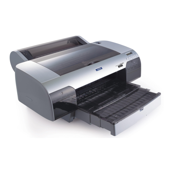
Chapter 1 Product Description Table of Contents 1.1 FEATURES 1.2 SPECIFICATIONS 1.2.1 Printing Specifications ........1-2 1.2.2 Paper Handling Specifications . - Page 8 List of Figures Figure 1-1. Exterior View of the Stylus Color Pro ..... 1-1 Figure 1-2. Nozzle Configuration ........1-2 Figure 1-3.
-
Page 9: Features
Stylus Pro Service Manual Product Description 1.1 FEATURE The Stylus Pro is a high-performance color ink jet printer with a small footprint and low cost. The main components of this printer are similar to the Stylus Color. The main features are:... -
Page 10: Specifications
Product Description Stylus Pro Service Manual 1.2 SPECIFICATIONS This section provides statistical facts and other detailed information for the printer. 1.2.1 Printing Specifications Print system: On demand ink jet system Nozzle configuration: 64 nozzles (16 4 staggered): monochrome 48 nozzles (16 3 staggered): color... -
Page 11: Table 1-2. Character Tables
ISO 8859-7 (Greek) ISO Latin 1T (Turkish) Bulgaria (Bulgaria) Not supported m Supported Note: These character tables are not supported for EPSON Roman T and EPSON Sans Serif H scalable fonts. Fonts: Bitmap LQ fonts r EPSON Roman (10 cpi/12 cpi/15 cpi/Proportional) -
Page 12: Paper Handling Specifications
Product Description Stylus Pro Service Manual 1.2.2 Paper Handling Specifications Feeding method: Friction feed paper is fed from the built-in auto sheet feeder (ASF). Notes: The following operations are not allowed: 1. Reverse feeding within 3 mm (0.12 in.) from the top edge of the paper or 16 mm (0.63 in.) from the bottom edge of the paper. -
Page 13: Figure 1-3. Printable Area For Cut Sheets
Stylus Pro Service Manual Product Description Printable area: Cut sheets (Left margin) (Right margin) (Top margin) Printable area (Bottom margin) Figure 1-3. Printable Area for Cut Sheets Note: A: Mnimum top margin = 3 mm (0.12 in.) B: Minimum left margin = 3 mm (0.12 in.) -
Page 14: Ink Cartridge Specifications
Product Description Stylus Pro Service Manual Adjust lever settings: The adjust lever on the carriage unit must be set to the proper position for the paper thickness, as shown in Table 1-5. Table 1-5. Adjust Lever Setting Lever Position Paper... -
Page 15: Environmental Conditions
Stylus Pro Service Manual Product Description Item 120 V Version 220 - 240 V Version Rated voltage 120 VAC 220 - 240 VAC Input voltage range 103.5 132 V 264 V Rated frequency range 60 Hz 60 Hz Input frequency range 49.5... -
Page 16: Reliability
Product Description Stylus Pro Service Manual 1.2.7 Reliability Total print volume: 75,000 pages (A4, letter) Printhead life: 1,000 million dots/nozzle 1.2.8 Safety Approvals Safety standards: 120 V version: UL1950 with D3, CSA22.2 # 950 with D3 220-240 V version: EN 60950 (TÜV, SEMKO, DEMKO,... -
Page 17: Interface Specifications
Stylus Pro Service Manual Product Description 1.3 INTERFACE SPECIFICATIONS The Stylus Pro is standard-equipped with an 8-bit parallel and serial interface. 1.3.1 Parallel Interface Specifications Data format: 8-bit parallel Synchronization: By STROBE pulse synchronization Handshaking: By BUSY and ACKNLG signals... -
Page 18: Table 1-8. Signal And Connector Pin Assignments For Parallel Interface
Product Description Stylus Pro Service Manual Table 1-8 shows connector pin assignments and signal functions of the 8-bit parallel interface. Table 1-8. Signal and Connector Pin Assignments for Parallel Interface Pin No. Signal Name I/O* Description The STROBE pulse is used to read data from the host computer. -
Page 19: Serial Interface Specifications
Stylus Pro Service Manual Product Description 1.3.2 Serial Interface Specifications Data format: RS-422 serial Synchronization: Asynchronous Handshaking: By DTR signal and X-ON/X-OFF protocol Table 1-9. DTR and X-ON/X-OFF Protocol State Buffer Space X-ON/X-OFF Busy Less than 512 bytes X-OFF Ready... -
Page 20: Operations
Product Description Stylus Pro Service Manual 1.4 OPERATIONS This section describes the basic operations of the printer. 1.4.1 Control Panel The control panel for this printer has 1 lock-type and 5 non lock-type pushbuttons, and 15 LED indicators for easy operation of the various printer functions. -
Page 21: Panel Operation At Power On
Stylus Pro Service Manual Product Description Indicators Operate On when the printer is on. Blinks during power on and off. Data On when print data is in the input buffer. Data and Pause lights blink if an error occurs. Paper Out On when the printer is out of paper. -
Page 22: Default Settings
Product Description Stylus Pro Service Manual 1.4.3 Default Settings The printer can save some printer setting parameters that define its functions at initialization. You can change these parameters using the printer’s default-setting mode. 1.4.3.1 Default Setting Items In default-setting mode, you can change settings listed in the table below. Activate default-setting mode by holding down the Economy/Condensed button while turning on the printer. -
Page 23: Table 1-14. Language Selection
Stylus Pro Service Manual Product Description Hold down the Economy/Condensed button and turn on the printer. The printer prints a sheet that shows the firmware version and describes how to select the language used to print messages. Press the Font button until the appropriate font LED is selected. The following table shows which language corresponds to which font LED. -
Page 24: Table 1-16. Character Table Selection
Product Description Stylus Pro Service Manual Table 1-16. Character Table Selection Paper Out Version Settings Operate LED Data LED Italic U.S.A. Italic France Italic Germany Blinks Italic U.K. Italic Denmark 1 Common Italic Sweden Blinks Italic Italy Blinks Italic Spain 1... -
Page 25: Error Conditions
Stylus Pro Service Manual Product Description 1.4.4 Error Conditions The printer can detect the various errors and indicate them with LEDs. Table 1-17. Error Indications No Ink Paper Out Economy Condensed Pause Error Data LED Cartridge Paper out No ink cartridge... -
Page 26: Main Components
Product Description Stylus Pro Service Manual 1.5 MAIN COMPONENTS The main components of the Stylus Pro are: Main control board (C164 MAIN Board) Power supply unit (C137 PSB/PSE Board) Control panel board (C137 PNL Board) Printer mechanism (M-4A10) Housing 1.5.1 Main Control Board (C164 MAIN Board) -
Page 27: Power Supply Board (C137 Psb/Pse Board)
Stylus Pro Service Manual Product Description 1.5.2 Power Supply Board (C137 PSB/PSE Board) The power supply board (C137 PSB/PSE Board) consists of an RCC switching regulator circuit. This board is equipped with a power switch, connected to the secondary circuit. Thus, if the printer is turned off, it can continue to operate to eject the paper and perform the head-capping operation. -
Page 28: Printer Mechanism (M-4A11)
Product Description Stylus Pro Service Manual 1.5.4 Printer Mechanism (M-4A11) The M-4A11 printer mechanism is equipped with a 64-nozzle black printhead and 48-nozzle color (CMY) printhead on the carriage unit. A resolution of 720 dpi is possible with special (non-absorbent) paper. - Page 29 Chapter 2 Operating Principles Table of Contents 2.1 OVERVIEW 2.2 OPERATING PRINCIPLES OF THE PRINTER MECHANISM 2.2.1 Printer Mechanism ......... . 2-1 2.2.2 Principles of the Printing Operation.
- Page 30 Figure 2-22. Paper Feed Motor Drive Circuit Diagram....2-18 Figure 2-23. Normal/EPSON Micro Dot Switching Block Diagram ..2-19 Figure 2-24.
-
Page 31: Overview
Stylus Pro Service Manual Operating Principles 2.1 OVERVIEW This section describes the operating principles of the printer mechanism and the electrical circuits of the Stylus Pro. 2.2 OPERATING PRINCIPLES OF THE PRINTER MECHANISM 2.2.1 Printer Mechanism The Stylus Pro is based on the Stylus Color printer. The Stylus Pro printer mechanism is composed of the printhead unit, paper feed mechanism, carriage drive mechanism, pump mechanism, and various sensors such as the Stylus Color’s. -
Page 32: Principles Of The Printing Operation
The printing mechanism of this printer uses a drop-on-demand ink jet system similar to the system used on all other EPSON ink jet printers. However, the printhead in this system is completely redesigned to make it more compact and ensure a high level of reliability, just as with the Stylus Color. The figure below shows the structure of the printhead and ink supply system. -
Page 33: Figure 2-3. Principles Of The Printing Operation
EPSON Micro Dot Printing Mode (Super 720 dpi Printing Mode) The Stylus Pro printer has a special printing mode, called the EPSON Micro Dot Printing mode. This printing mode can be selected on command from the host computer. Using this printing mode can improve the quality of output because it eliminates the banding that can sometimes occur in normal mode. -
Page 34: Carriage Drive Mechanism
Operating Principles Stylus Pro Service Manual 2.2.3 Carriage Drive Mechanism The timing belt attached to the base of the carriage unit is driven by the carriage motor, causing the carriage unit to move along the carriage guide shaft from left to right, or vice versa. The carriage drive motor on this printer is a 4-phase, 200-pole, hybrid-type stepping motor mechanism, allowing the printer to stop the carriage or change the carriage movement at any position. -
Page 35: Cr Hp Sensor
Stylus Pro Service Manual Operating Principles The platen gap adjust lever, which is attached to the carriage unit, needs to be set to the appropriate position for the paper thickness. To change the platen gap, put the printer in the PAUSE state, then press the Font button while holding down the Alt button. -
Page 36: Table 2-5. Drive Terms
Operating Principles Stylus Pro Service Manual Table 2-5. Drive Terms Current Value (mA) Frequency Mode (pps) Acceleration/ Constant Rush Hold Deceleration Paper loading 1600 970/750 ASF feed 1600 970/750 Paper feed — / — — Pump Drive 1 1800 1380/1380... -
Page 37: Ink System
Stylus Pro Service Manual Operating Principles 2.2.5 Ink System This printer’s ink system is composed of the following mechanisms: Ink cartridge Pump mechanism Cap mechanism Waste ink drain tank Wiping mechanism The figure below shows a diagram of the ink system. -
Page 38: Pump Mechanism
Operating Principles Stylus Pro Service Manual 2.2.6 Pump Mechanism The paper feed motor drives the pump mechanism when the transmission gear is moved to the position where the paper feed motor engages the pump mechanism gear trains, when the carriage unit is at the ink system home position. - Page 39 Stylus Pro Service Manual Operating Principles Drive: Pump Mechanism Carriage Figure 2-10. Paper Feed Mechanism Drive: Switch Lever Set Carriage D/E Reset Lever D/E Lever Figure2-11. Switch Lever Reset Rev.A...
-
Page 40: Table 2-6. Pump Mechanism Operation
Operating Principles Stylus Pro Service Manual Table 2-6. Pump Mechanism Operation PF Motor Rotational Direction Operation r Color absorption Clockwise (CW) r Wiper reset forward rotation r Carriage lock reset r Monochrome absorption Counterclockwise (CCW) r Wiper set backward rotation r Carriage lock set The pump draws ink from the printhead nozzles and drains it into the waste ink drain tank. -
Page 41: Cap Mechanism
Stylus Pro Service Manual Operating Principles 2.2.7 Cap Mechanism The cap mechanism prevents printhead nozzles from drying and keeps bubbles from forming inside the nozzle while the printer is not in use. The printer performs this operation automatically when print data is not received, when printer power is turned off, and during printing or ink system operations. -
Page 42: Operating Principles Of The Electrical Circuits
Operating Principles Stylus Pro Service Manual 2.3 OPERATING PRINCIPLES OF THE ELECTRICAL CIRCUITS The Stylus Color Pro contains the following circuit board units: C164 MAIN Board (main control circuit board). C137 PSB/PSE Board (power supply circuit board). This board is the same as Stylus Color’s C137 PNL (control panel board). - Page 43 Stylus Pro Service Manual Operating Principles The figure below shows a block diagram of the power supply circuit (C137 PSB/PSE). The power switch is equipped with a secondary circuit that allows the CPU to remain active for a while after the printer is turned off.
-
Page 44: Operating Principles Of The Main Control Circuit
Operating Principles Stylus Pro Service Manual 2.3.2 Operating Principles of the Main Control Circuit The main control circuit for this printer is the C164 MAIN Board. This circuit is controlled by a 16-bit H8/3003 CPU (IC1), running at 14.7456 MHz. The CPU has a unique architecture, capable of handling data on the data bus at either an 8-bit or 16-bit bus width. -
Page 45: Reset Circuits
Stylus Pro Service Manual Operating Principles 2.3.2.1 Reset Circuits The C164 MAIN Board contains 2 reset circuits: the +5 V monitor reset circuit and the +35 V monitor reset circuit. The +5 V monitor reset circuit monitors the voltage level of the +5 V line (logic line), using reset IC PST592D (IC13), and outputs a reset signal to the CPU (IC1) and the E05E09 gate array (IC2) when the voltage level drops below +4.2 V. -
Page 46: Carriage Motor Drive Circuit
Operating Principles Stylus Pro Service Manual 2.3.2.3 Carriage Motor Drive Circuit The carriage motor drive IC SLA7041MS (IC15) outputs a constant current to drive the carriage motor for the printer mechanism. Gate array E05B09 (IC2) decides the motor phase and speed and then sends a signal to the carriage motor driver IC (SLA7041MS) using the 4-bit serial transmission line. -
Page 47: Operating Principles
Stylus Pro Service Manual Operating Principles The following figure shows 4-bit serial data and how this data is transferred by the SLA7041MS driver. The step time of the reference voltage is determined by the interval time of the strobe pulse. -
Page 48: Paper Feed Motor Drive Circuit
Operating Principles Stylus Pro Service Manual 2.3.2.4 Paper Feed Motor Drive Circuit The paper feed motor for this printer drives the following mechanisms: Paper feed mechanism Paper pickup mechanism Pump mechanism Driver IC SLA7041MS (IC14) drives the paper feed motor by a constant current. The operation principle is same as for the carriage motor drive circuit. -
Page 49: Printhead Drive Circuit
Normal Dot / EPSON Micro Dot Printing Mode The Stylus Color Pro produces two types of ink ejection (normal print mode and EPSON Micro Dot Mode). The signals for switching ink ejection modes are “SELM” (for normal dot printing) and “SELN” (for EPSON Micro Dot printing). -
Page 50: Figure 2-25. Printhead Drive Circuit Block Diagram
Operating Principles Stylus Pro Service Manual E05B09 (IC2 ) C O M 1 - 8 B P W C Common Driver SED5620 D (U1) B P W D L A T DO64 -49 Ro w A B L A T... -
Page 51: Dram Refresh Controller
Stylus Pro Service Manual Operating Principles 2.3.2.7 DRAM Refresh Controller The CPU is equipped with a refresh controller in its internal controller. This CPU controller can contact the 16-bit length IC5 DRAM, which is a 2 CAS type. The following table lists the junction method between the H8 CPU and the 2 CAS DRAM. -
Page 52: Ink System Management
Operating Principles Stylus Pro Service Manual 2.4 INK SYSTEM MANAGEMENT This section explains how the ink system is controlled to protect the printhead and the ink supply system and to ensure high-quality output. Ink system control is composed of the following operations:... - Page 53 Stylus Pro Service Manual Operating Principles This operation is performed when the Alt button is held down for more than 3 seconds (the Pause LED lights); the carriage then moves to the ink cartridge replacement position. 10. Wiping Operation 1 This operation eliminates dust from the nozzle plate before performing ink absorption.
-
Page 54: Counter
Operating Principles Stylus Pro Service Manual 2.4.2 Counter EEPROM LE93C46 (IC12) on the main board stores certain counter and timer values that are used for controlling the ink system operation. 2.4.2.1 Protect Counter The value of protect counter A is stored into the EEPROM on the main board, and while the printer is on, this data is stored in the RAM on the main board. - Page 55 Chapter 3 Disassembly and Assembly Table of Contents 3.1 OVERVIEW 3.1.1 Precautions for Disassembling the Printer ..... . 3-1 3.2 DISASSEMBLY AND ASSEMBLY 3.2.1 Upper Case Removal .
-
Page 56: Overview
Stylus Pro Service Manual Disassembly and Assembly 3.1 OVERVIEW This section describes procedures for disassembling the main components of this printer. Unless otherwise specified, the disassembled unit or components can be reassembled by reversing the disassembly procedure. Therefore no assembly procedures are included. Precautions for any disassembly or assembly procedure are described under the heading “Disassembly/Assembly Points.”... -
Page 57: Disassembly And Assembly
Disassembly and Assembly Stylus Pro Service Manual 3.2 DISASSEMBLY AND ASSEMBLY Follow the precautions in Section 3.1.1 when disassembling the printer. This section consists of the subheads shown in the diagram below. See the exploded view of the printer in the Appendix, if necessary. -
Page 58: Upper Case Removal
Stylus Pro Service Manual Disassembly and Assembly 3.2.1 Upper Case Removal 1. 1. Remove the printer cover by releasing the 2 tabs holding it to the upper case. Remove the paper support by releasing the 2 tabs holding it to the lower case. -
Page 59: Power Supply Unit (C137 Psb/Pse Board) Removal
Disassembly and Assembly Stylus Pro Service Manual 3.2.2 Power Supply Unit (C137 PSB/PSE Board) Removal Remove the upper case. (See Section 3.2.1.) Disconnect the cables from connector CN1 on the C137 PSB/PSE Board and from CN5 on the C164 MAIN Board. -
Page 60: Main Controller (C164 Main Board) Removal
Stylus Pro Service Manual Disassembly and Assembly 3.2.3 Main Controller (C164 MAIN Board) Removal Remove the upper case. (See Section 3.2.1.) Remove the P/S shield plate from the upper shield plate. Remove 2 CBS (M3 8) screws securing the upper cover connector to the I/F grounding plate and remove the upper cover connector (Type-B interface cover). - Page 61 Disassembly and Assembly Stylus Pro Service Manual r When you replace the main board, initialize the EEPROM contents as follows; 1) Reassemble the printer. 2) Turn the printer ON while hold down [Alt], [Font], [Load/Eject] and [Pause] buttons on the control panel.
-
Page 62: Printer Mechanism (M-4A11) Removal
Stylus Pro Service Manual Disassembly and Assembly 3.2.4 Printer Mechanism (M-4A11) Removal Remove the upper case. (See Section 3.2.1.) Remove the power supply unit. (See Section 3.2.2.) Remove the main controller. (See Section 3.2.3.) Remove the 4 CBS (M4 14) screws and take out the printer mechanism. -
Page 63: Printer Mechanism Disassembly
Disassembly and Assembly Stylus Pro Service Manual 3.2.5 Printer Mechanism Disassembly The procedures described in this section explain how to remove the components within the printer mechanism. 3.2.5.1 Printhead Unit Removal Remove the printer mechanism. (See Section 3.2.4.) Move the carriage to the middle of the printer while pressing the hook that fixes the carriage unit to the home position. - Page 64 Stylus Pro Service Manual Disassembly and Assembly Remove the CBB (M3 11) screw (under CR cap cover) and a plain washer securing the monochrome and color printheads to the carriage base. CR Cap Cover Ink Cartridge Holder CBB (M3x11) CBB (M3x11)
- Page 65 Disassembly and Assembly Stylus Pro Service Manual Printhead Nozzles R, M Color Printhead Monochrome Printhead R: Normal Dot Resistance Value M: Micro Dot Resistance Value Figure 3-10. Printhead Resistance Value r When removing or changing the black head, you need to make the following adjustments: 1.
-
Page 66: Carriage Unit Removal
Stylus Pro Service Manual Disassembly and Assembly 3.2.5.2 Carriage Unit Removal Remove the printer mechanism. (See Section 3.2.4.) Move the carriage to the left side of the printer while pressing the hook that fixes the carriage to the home position. -
Page 67: Pump Unit Removal
Disassembly and Assembly Stylus Pro Service Manual 3.2.5.3 Pump Unit Removal Remove the printer mechanism. (See Section 3.2.4.) Remove the carriage unit. (See Section 3.2.5.2.) Remove the CBS (M3 6) screw securing the pump unit to the bottom frame. Push the pump unit outward while releasing the tab at the bottom side of the pump unit, and then lift up the pump unit. -
Page 68: Cleaner Head Replacement
Stylus Pro Service Manual Disassembly and Assembly 3.2.5.4 Cleaner Head Replacement Remove the printer mechanism. (See Section 3.2.4.) Use tweezers to unhook the cleaner head from the hook on the cleaning lever. Keeping the cleaner head clean is extremely important to keep the ink injection system working properly in the printhead, and it directly affects printing quality. -
Page 69: Cr Motor Removal
Disassembly and Assembly Stylus Pro Service Manual 3.2.5.5 CR Motor Removal Remove the printer mechanism. (See Section 3.2.4.) Release the timing belt. (See Section 3.2.5.2.) Remove the 3 screws securing the CR motor to the upper frame, and then remove the CR motor. -
Page 70: Carriage Home Position Sensor Removal
Stylus Pro Service Manual Disassembly and Assembly 3.2.5.7 Carriage Home Position Sensor Removal Remove the printer mechanism. (See Section 3.2.4.) Disconnect the sensor cable from the carriage home position sensor. Unhook the 3 notches securing the carriage home position sensor to the upper frame. Then remove the carriage home position sensor. -
Page 71: Paper Feed Roller Assembly Removal
Disassembly and Assembly Stylus Pro Service Manual 3.2.5.9 Paper Feed Roller Assembly Removal Remove the printer mechanism. (See Section 3.2.4.) Remove the carriage unit. (See Section 3.2.5.2.) Remove the tension spring holding the tension roller assembly to the sub frame. -
Page 72: Upper Frame Removal
Stylus Pro Service Manual Disassembly and Assembly 3.2.5.10 Upper Frame Removal Remove the printer mechanism. (See Section 3.2.4.) Remove the carriage unit. (See Section 3.2.5.2.) Remove the E-ring securing the knob shaft to the sub frame; then remove the knob with the knob shaft from the right side frame. -
Page 73: Drain Ink Pad Removal
Disassembly and Assembly Stylus Pro Service Manual 3.2.6 Drain Ink Pad Removal The procedures described in this section explain how to remove the drain ink pad when the protect counter value reaches its maximum, and the printer displays a maintenance request error. (Refer to Section 2.4.2.) Remove the upper case. - Page 74 Chapter 4 Adjustment Table of Contents 4.1 OVERVIEW 4.1.1 Destination Data Writing Operation ......4-2 4.1.2 Bi-D (Bidirectional Printing) Alignment Adjustment.
-
Page 75: Table 4-1. Required Adjustments
Stylus Pro Service Manual Adjustment 4.1 OVERVIEW This section describes adjustments required when the printer is disassembled and assembled after repair. Since this printer has both black and color heads, it needs new adjustments not required for previous printers. Refer to the following table to perform the appropriate adjustments. -
Page 76: Destination Data Writing Operation
Adjustment Stylus Pro Service Manual 4.1.1 Destination Data Writing Operation The setup value that specifies the destination setting is stored in the EEPROM on the C164 MAIN board. This setup value must be rewritten to the EEPROM when the main board or the EEPROM chip is replaced. -
Page 77: Bi-D (Bidirectional Printing) Alignment Adjustment
Stylus Pro Service Manual Adjustment 4.1.2 Bi-D (Bidirectional Printing) Alignment Adjustment The bidirectional alignment is required when the printer mechanism, main board, or the printhead (board) is replaced. Performing this adjustment determines a compensation value to rectify any deviation in the print position. -
Page 78: Head Gap Adjustment (Black And Color Head)
Adjustments Stylus Pro XL 4.1.3 Head Gap Adjustment (Black and Color Head) The head gap adjustment is required when the printer mechanism, main board, or printhead (board) is replaced or diassembled. This adjustment calibrates the head drive timing between the black and color head. -
Page 79: Black Head Angle Adjustment
Stylus Pro XL Adjustments 4.1.4 Black Head Angle Adjustment The black head angle adjustment is required when the black head is replaced or disassembled. If this adjustment is not correct, a white banding problem may occur, or the color head timing may not match the black head timing. -
Page 80: Figure 4-4. Black Head Angle Adjustment Sample
Adjustments Stylus Pro XL Connect the PC to the target printer, and turn the printer on. Execute BASIC on the PC and run the program “VERxxx.BAS.” 1. Destination Setting 2. Head Angle Confirmation Pattern Printing (Black Head Spacer Selection) 3. Head Vertical Position Confirmation 4. -
Page 81: Figure 4-6. Removing The Rubber Cap
Stylus Pro XL Adjustments Turn the printer power off now. Manually move the carriage to the center while pressing the carriage lock lever, and remove the two ink cartridges. Remove the rubber cap covering the head screw at the side of color ink cartridge. Then loosen (but do not remove) 3 screws. - Page 82 Adjustments Stylus Pro XL 11. After replacing the angular spacer, reassemble the ink cartridge holder and reinstall the ink cartridges. Use the BASIC program to verify the angle of the black head. Confirm the angle by performing the steps 1 to 6 again, and if the angle is wrong, perform the adjustment again until the head angle is correct.
-
Page 83: Black - Color Head Vertical Adjustment
Stylus Pro XL Adjustments 4.1.5 Black - Color Head Vertical Adjustment This adjustment calibrates the vertical position between the black head and the color head. Align the top nozzles (both nozzle #1 on the black head and nozzle #1 on the color head). You can make this adjustment by using only the linear spacers for the black head. - Page 84 Adjustments Stylus Pro XL In Figure 4-10, the vertical position is correct when both the magenta line and the black line are aligned (as shown in position OK (0)). If the vertical position is correct, turn off the printer. If the black and magenta lines are not aligned, perform the vertical adjustment as described in steps 5-10.
- Page 85 Stylus Pro XL Adjustments Change the linear spacers (2 spacers for the monochrome head only) with new ones, referring the figure below. (Replace linear spacers using tweezers to push the head base toward the rear.) Carriage Unit Black Head 1: Push He ad B ase Angu lar Spacer Platen Gap...
-
Page 86: Color Head Angle Adjustment
4.1.6 Color Head Angle Adjustment The color head angle adjustment is required when the color head is replaced or disassembled. If this adjustment is not correct, a white banding problem may occur, or the black head timing may not match the color head timing. The following figure illustrates the color head angle adjustment. The color head angle is adjusted by the angular spacer. - Page 87 Stylus Pro XL Adjustments Angular spacers for the color head come in five thicknesses, each having its own shape. The following figure shows the relationship between the shape and thickness. Since the color head is not equipped with a linear spacer, the angle adjustment is decided only by the angular spacer (specifically designed for the color head), which is placed under the left side of the head base.
- Page 88 Adjustments Stylus Pro XL Ru bber Cap Screw 1 Screw 2 Screw 3 Figure 4-16. Removing the Rubber Cap Remove the rubber cap covering the head screw at one side of color ink cartridge. Then loosen (but do not remove) 3 screws. (Refer to the figure below.) Replace the angular spacer on the left side with a new one, referring the figure below.
- Page 89 Stylus Pro XL Adjustments Rerun the BASIC program and choose “Head Angle Confirmation Pattern” again by typing 2 and ENTER. Then verify that the confirmation sample is correct. Carriage Unit Color Head 1: Push Head Base Platen Gap Adjust Lever Angular Spacer 2: Replace (one side only)
-
Page 90: Platen Gap Adjustment
Adjustments Stylus Pro XL 4.1.7 Platen Gap Adjustment This adjustment is required when the carriage unit is replaced or removed from the printer mechanism. Adjust the distance between the printhead nose and the paper surface to 1.1 mm. Attach a thickness gauge (commercially available) to the left side adjustment position on the paper guide plate, as shown in the figure below, so that one side hooks the paper feed pinch roller unit. -
Page 91: Internal Timer Reset Operation
Stylus Pro XL Adjustments Move the carriage manually to the right adjustment position and repeat steps 3 and 4, referring to Figures 4-18 and 4-19. Carriage Roller 0.04 mm Thickness Eject Frame Gauge Figure 4-19. Confirming the Gap 4.1.8 Internal Timer Reset Operation This operation is required when the M-4A60 printer mechanism is replaced. - Page 92 Chapter 5 Troubleshooting Table of Contents 5.1 OVERVIEW 5.2 UNIT LEVEL TROUBLESHOOTING 5.2.1 Printer Does Not Operate at Power on ......5-4 5.2.2 Error is Detected.
-
Page 93: Overview
Stylus Pro Service Manual Troubleshooting 5.1 OVERVIEW The printer may exhibit different symptoms for the same problem, which makes troubleshooting more difficult. This section, however, provides simple and effective ways to facilitate troubleshooting. The following flowchart illustrates the main steps in the troubleshooting process. - Page 94 Troubleshooting Stylus Pro Service Manual Table 5-2. Sensor Status Sensor Point Signal Level Status H (5 V) Paper exists CN8 / PE Sensor Pin 1 to Pin 2 L (GND) No paper (paper end) L (GND) Black cartridge exists CN11 /...
-
Page 95: Unit Level Troubleshooting
Stylus Pro Service Manual Troubleshooting 5.2 UNIT LEVEL TROUBLESHOOTING When a problem occurs, you can identify the defective unit by the symptoms exhibited. The table below lists the symptoms of certain problems. Once the problem is identified, refer to the flowchart that corresponds to the problem. -
Page 96: Printer Does Not Operate At Power On
Troubleshooting Stylus Pro Service Manual 5.2.1 Printer Does Not Operate at Power On START Is the AC Use the correct input voltage input voltage. correct ? Replace the fuse Has fuse and disconnect (F1) on the C137 CN5 on the C164 PSB/PSE MAIN board. -
Page 97: Error Is Detected
Stylus Pro Service Manual Troubleshooting 5.2.2 Error is Detected START Identify the type of error indicated. (See Table 5-3.) Turn the printer off and try to Carriage error move the carriage manually. Does the carriage move smoothly ? Replace the ink... -
Page 98: Failure Occurs During Printing
Troubleshooting Stylus Pro Service Manual 5.2.3 Failure Occurs During Printing START Run the self-test. Does the self- test print? Are all cables connected to C164 MAIN firmly ? Is print quality bad ? Connect the cables Adjust the correctly. bidirectional... -
Page 99: Troubleshooting
Stylus Pro Service Manual Troubleshooting 5.2.4 Printer Does Not Feed the Paper Correctly START Is paper loaded in the sheet feeder correctly ? Load the paper correctly. Verify that the Does a paper path is clear. paper jam Also confirm that... -
Page 100: Control Panel Operation Is Abnormal
Troubleshooting Stylus Pro Service Manual 5.2.5 Control Panel Operation is Abnormal START Is the control panel connected properly ? Connect the control panel correctly. Is the problem corrected ? Replace the control panel. Is the problem corrected ? Replace the C164 MAIN board. -
Page 101: Unit Repair - C137 Psb/Pse Board
Stylus Pro Service Manual Troubleshooting 5.3 UNIT REPAIR — C137 PSB/PSE BOARD This section describes problems related to the power supply board (C137 PSB/PSE). The table below provides various symptoms, likely causes, and checkpoints. The checkpoints are waveforms, resistances, and other values to be checked to evaluate the operation of each component. -
Page 102: Unit Repair - C164 Main Board
Troubleshooting Stylus Pro Service Manual 5.4 UNIT REPAIR — C164 MAIN BOARD This section describes the problems related to the main controller board (C164 MAIN). The table below provides various symptoms, likely causes, and checkpoints. The checkpoints are waveforms, resistances, and other values to be checked to evaluate the operation of each component. - Page 103 Stylus Pro Service Manual Troubleshooting Table 5-7. Repair of the C164 MAIN (Continued) Symptom Cause Checkpoint Solution Condition Check the output signal at pin 1, 8 Carriage does The carriage Replace IC15 is defective. or 11, 18 of IC15. not operate does not IC15.
-
Page 104: Unit Repair - Printer Mechanism (M-4A11)
Troubleshooting Stylus Pro Service Manual 5.5 UNIT REPAIR — PRINTER MECHANISM (M-4A11) Any problems related to the printer mechanism should be repaired according to the troubleshooting procedures in Table 5-8. Table 5-8. Repair of the Printer Mechanism Symptom Condition Cause... - Page 105 Stylus Pro Service Manual Troubleshooting Table 5-8. Repair of the Printer Mechanism (Continued) Symptom Condition Cause Checkpoint Solution The head cable is Check whether the head Reconnect the disconnected. cable is disconnected. head cable. The head cable is Replace the head cable to...
- Page 106 Troubleshooting Stylus Pro Service Manual Table 5-8. Repair of the Printer Mechanism (Continued) Symptom Condition Cause Checkpoint Solution Remove any Foreign substance Visually check the paper is lodged in the foreign path. paper path. substance. Paper is not Paper feeding Replace Paper is not fed.
- Page 107 Chapter 6 Maintenance Table of Contents 6.1 PREVENTIVE MAINTENANCE 6.2 SERVICE MAINTENANCE 6.2.1 Printhead Cleaning......... . 6-2 6.2.2 Waste Ink Drain Tank Replacement .
-
Page 108: Preventive Maintenance
Stylus Pro Service Manual Maintenance 6.1 PREVENTIVE MAINTENANCE Although this printer is designed so that no specific maintenance is required on a regular basis, it is recommended that you clean the printer thoroughly whenever you get a chance to do so. You can clean: Outer case Use a soft, clean cloth, dampened with mild detergent, if necessary. -
Page 109: Service Maintenance
Maintenance Stylus Pro Service Manual 6.2 SERVICE MAINTENANCE Certain maintenance is required when the printer detects an error or when a decline in print quality is observed. 6.2.1 Printhead Cleaning If print quality deteriorates, clean the printhead using the built-in printhead cleaning function. The printer also has an automatic printhead cleaning cycle to ensure the proper nozzle operation for ink injection as well as to preserve its best condition. -
Page 110: Lubrication And Adhesive
The printer must be lubricated properly when it is disassembled for component replacement, or if mechanical noise exceeds a certain level. EPSON recommends only the lubricants listed in the table below for this printer, both of which have been tested extensively and comply with the requirements of this printer mechanism. - Page 111 Maintenance Stylus Pro Service Manual Do not apply too much lubricant, as it may stain the mechanism as well as a cause a mechanism malfunction. Rev.A...
- Page 112 Stylus Pro Service Manual Maintenance Figure 6-1. Lubrication Points and Adhesive Points (1) Rev.A...
- Page 113 Maintenance Stylus Pro Service Manual Lubrication Point Adhesive Point Figure 6-2. Lubrication Points and Adhesive Points (2) Rev.A...
- Page 114 Appendix Table of Contents A.1 CONNECTOR SUMMARY A.2 CIRCUIT DIAGRAMS A.3 CIRCUIT BOARD COMPONENT LAYOUTS A-14 A.4 EXPLODED DIAGRAMS A-17 LIST OF FIGURES Figure A-1. Interconnection of Major Components ....A-1 Figure A-2.
- Page 115 Stylus Pro Service Manual Appendix A.1 CONNECTOR SUMMARY The figure below shows the interconnection between the major components of the Stylus Color Pro. C137 PSB/PSE AC Input Printhead C N 2 Unit CN 5 Parallel Color I/ F Ty pe B...
- Page 116 Rev.A Table A-1. Connector Summary Board Location Pins Description C164 MAIN Centronics parallel I/F Type B parallel I/F RS-422 serial I/F Power supply from PS board Carriage motor phase output PF/PM motor phase output Paper end sensor Carriage home position sensor CN10 Control panel (to C137 PNL) CN11...
- Page 117 Stylus Pro Service Manual Appendix Table A-3. Connector Pin Assignments – CN2 Name Description +5 V Power supply for I/F drive Transmit data Ready signal READY Receive data — Not connected Reset signal RESET Inhabit signal Command request signal CMREQ...
- Page 118 Rev.A Table A-5. Connector Pin Assignments – CN5 Name Description Power scan signal +35 V Head common driver for common drive circuit — Ground 7, 8 Power supply for logic system Table A-6. Connector Pin Assignments – CN6 Name Description Phase A drive signal CR/A Phase /A drive signal...
- Page 119 Stylus Pro Service Manual Appendix Table A-8. Connector Pin Assignments – CN8 Name Description Paper out state detection signal — Ground Table A-9. Connector Pin Assignments – CN9 Name Description Home position detection signal — Ground Sensor drive power supply Table A-10.
- Page 120 Rev.A Table A-11. Connector Pin Assignments – CN11 Name Description — Ground BCLK Clock signal for black head — Ground BLAT Latch signal for black head — Ground Black head serial data output — Ground Black cartridge out sensor +5 V Power supply for cartridge out sensor —...
- Page 121 Stylus Pro Service Manual Appendix A.2 CIRCUIT DIAGRAMS Figure A-2. C164 MAIN Board Circuit Diagram (1) Rev.A...
- Page 122 *5 IC6, Q2, R135 and CN13 are not mounted on the C164 MAIN Board (Stylus Pro)
- Page 123 Stylus Pro Service Manual Appendix Figure A-3. C164 MAIN Board Circuit Diagram (2) Rev.A...
- Page 124 Stylus Pro Service Manual Appendix Figure A-4. C137 PSB Board Circuit Diagram Rev.A A-11...
- Page 125 Rev.A A-12 Figure A-5. C137 PSE Board Circuit Diagram A-12 Rev.A...
- Page 126 Stylus Pro Service Manual Appendix Figure A-6. C137 PNL Board Circuit Diagram Rev.A A-13...
- Page 127 Rev.A A-14 A.3 CIRCUIT BOARD COMPONENT LAYOUTS Figure A-7. C164 MAIN Board Component Layout A-14 Rev.A...
- Page 128 Stylus Pro Service Manual Appendix Figure A-8. C137 PSB/PSE Board Component Layout Rev.A A-15...
- Page 129 Rev.A A-16 Figure A-9. C137 PNL Board Component Layout A-16 Rev.A...
- Page 130 Stylus Pro Service Manual Appendix A.4 EXPLODED DIAGRAMS Figure A-10. Stylus Color Pro Exploded Diagram (1) Rev.A A-17...
- Page 131 Rev.A A-18 Figure A-11. Stylus Color Pro Exploded Diagram (2) A-18 Rev.A...
- Page 132 Stylus Pro Service Manual Appendix Figure A-12. Stylus Color Pro Exploded Diagram (3) Rev.A A-19...
- Page 133 Rev.A A-20 Table A-13. Part No. Reference Table Ref. Description PPL Name Lower Housing HOUSING,LOWER Foot FOOT Lower Shield Plate SHIELD PLATE,LOWER Upper Shield Plate SHIELD PLATE,UPPER Power Supply Shield Plate SHIELD PLATE,P/S Grounding Plate GROUNDING PLATE Paper Support Cover COVER,PAPER SUPPORT Upper Housing HOUSING UPPER...
- Page 134 Stylus Pro Service Manual Appendix Harness HARNESS Panel Board Assembly BOARD ASSY.,PANEL Printer Mechanism PRINTER MECHANISM Driven Pulley PULLEY,DRIVEN Base Frame Assembly FRAME ASSY.,BASE PE Detector DETECTOR,PE Left Frame Assembly FRAME ASSY.,LEFT Middle Frame Assembly FRAME ASSY.,MIDDLE Right Main Frame...
- Page 135 Rev.A A-22 Table A-13. Part No. Reference Table (Continued) Ref. Description PPL Name Oil Pad OIL PAD Knob Lever LEVER,KNOB CR Stepping Motor STEPPING MOTOR,CR B CR Cover Assembly COVER ASSY.,CR;B CR Guide Ground Spring GROUND SPRING,CR,GUIDE CR Stopper Lever LEVER,CR,STOPPER CR Damper DAMPER,CR...
- Page 136 Stylus Pro Service Manual Appendix Table A-13. Part No. Reference Table (Continued) Ref. Description PPL Name PF Spring Cap CAP,SPRING,PF Hopper Cam CAM,HOPPER Clutch Cam CAM,CLUTCH Anti-static Brush ANTI-STATIC BRUSH Pad Holder Assembly HOLDER ASSY.,PAD;C Edge Guide EDGE GUIDE Edge Guide Pressing Plate...
- Page 137 Rev.A A-24 Compression Spring COMPRESSION SPRING,900 Compression Spring COMPRESSION SPRING,180 Extension Spring EXTENSION SPRING,200 Torsion Spring TORSION SPRING,10400 Plain Washer PLAIN WASHER 4x0.5x8 Plain Washer PLAIN WASHER 3x0.5x7 Plain Washer PLAIN WASHER 8x0.5x15 Plain Washer PLAIN WASHER 4.2x1x11 Plain Washer PLAIN WASHER 6x0.7x12 Plain Washer PLAIN WASHER 6.5x1x18...
- Page 138 EPSON OVERSEAS MARKETING LOCATIONS EPSON AMERICA, INC. EPSON DEUTSCHLAND GmbH 20770 Madrona Avenue, Zülpicher Straße 6, 40549 Düsseldorf P.O. Box 2842 F.R. Germany Torrance, CA 90509-2842 Phone: 0211-56030 Phone: (800) 922-8911 Fax : 0211-504-7787 Fax : (310) 782-5220 EPSON UK LTD.
- Page 139 EPSON Printed in Japan 95.05-30-A.
Need help?
Do you have a question about the Stylus Pro and is the answer not in the manual?
Questions and answers