
Related Manuals for Elmo Visual Presenter HV-7100SX


Summary of Contents for Elmo Visual Presenter HV-7100SX
- Page 1 VISUAL PRESENTER HV-7100SX INSTRUCTION MANUAL Please read this instruction manual carefully before using this product and keep it for future reference.
-
Page 2: Important Safeguards
IMPORTANT SAFEGUARDS I Read Instructions – All the safety and operating instructions should be read before the appliance is operated. I Retain Instructions – The safety and operating instructions should be retained for future reference. I Heed Warnings – All warnings on the product and in the operating instructions should be adhered to. - Page 3 I Grounding or Polarization – This product may be equipped with either a polarized 2-wire AC line plug (a plug having one blade wider than the other) or a 3-wire grounding type plug, a plug having a third (grounding) pin. The 2-wire polarized plug will fit into the power outlet only one way.
- Page 4 I Damage Requiring Service – Unplug this product from the wall outlet and refer servicing to qualified service personnel under the following conditions: G When the power-supply cord or plug is damaged. G If liquid has been spilled, or objects have fallen into the product.
- Page 5 lightning flash arrowhead symbol, within an equilateral triangle, is intended to alert the user to the presence of uninsulated "dangerous SA 1965 voltage" within the product's enclosure that may be of sufficient magnitude to constitute a risk of electric shock to persons.
- Page 6 BEFORE YOU USE I Use this product under the rated electrical conditions. I Do not leave this product under direct sunlight or by heaters, or this product may be discolored, deformed, or damaged. I Do not place this product in any humid, dusty, windy or vibrating location.
-
Page 7: Table Of Contents
3. MOUSE Mouse Operation ...14 4. SETTING UP AND CONNECTION Setting Up...15 Connection to Monitor and Projector ...15 Connection to the analog RGB-out terminal ...16 Connection to the composite video-out terminal ...16 Connection to the S video-out terminal ...16 Analog RGB Signal ...16 Signal allocation ...16... - Page 8 1. PART NAMES AND FUNCTIONS 2. WIRELESS REMOTE CONTROL 3. MOUSE 4. SETTING UP AND CONNECTION 5. STORING 6. OPERATION PROCEDURES 7. VARIOUS FUNCTION AND OPERATIONS 8. OSD 9. RS-232C SPECIFICATIONS 10. TROUBLESHOOTING HINTS 11. SPECIFICATIONS CONTENTS Preset Operation ...33 Image Memory ...34 Splitting the Screen ...35 F.A.M.
-
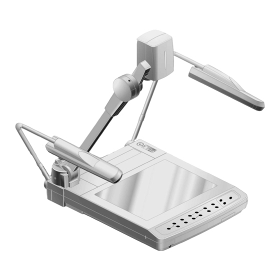
Page 9: Part Names And Functions Appearance
PART NAMES AND FUNCTIONS Appearance Camera Head Infrared Sensor Lighting Unit Column Lighting Unit Arm Column Lock Button Press this button to raise/fold the column. Stage Base Lamp Lamp Arm Upper Lamp Scroll Mouse Infrared Emitting Part Wireless Remote Control Pocket for Wireless Remote Control Front Operation Panel... -
Page 10: Front Operation Panel
Front Operation Panel MONITOR OUTPUT RGB1 MAIN RGB2 F.A.M. Monitor Output Selection Name Pause Iris White Balance Monitor Output Selection F.A.M. (Frame Accumulate Mode) Image Rotation Posi/Nega Conversion Lamp Contrast Zoom Auto Focus Pause Iris WHITE PAUSE IRIS OPEN CLOSE AUTO/MANUAL BALANCE F.A.M. -
Page 11: Rear Panel
Image is output when this terminal is Analog RGB-out connected to RGB input equipment Terminal [OUTPUT . RGB OUT] (e.g., LCD projector, multi-sync monitor). Input image is output through analog Analog RGB-in Terminal RGB-out terminal and video-out terminal [INPUT . RGB1] when the input selection is set at RGB1. - Page 12 Name Analog RGB-in Terminal 2 [INPUT . RGB2] Stereo Audio Input Terminal 1/2 DIP Switch Wireless Remote Control PAUSE PRESET . SET PRESET . CALL POSI/NEGA COLOR/B&W MONITOR OUTPUT . MAIN ZOOM . TELE ZOOM . WIDE IRIS . NORMAL IRIS .
- Page 13 Button Name To change the setting between still image PAUSE and video. ELECTRONIC To double the image size. ENLARGEMENT ARROWS To scroll the screen during magnification (electronic enlargement) mode. This button is also used to move the pointer when it appears. MEMORY NO.
-
Page 14: Wireless Remote Control
WIRELESS REMOTE CONTROL Receivable Range Point the infrared emitting part of the wireless remote control at the infrared sensor of this product, and press the button for desired function. The receivable range may be narrowed when the Presenter is placed under sunlight, near an inverter fluorescent lamp or in any other unfavorable surroundings. -
Page 15: Mouse
Use the attached mouse. If another mouse is used, the normal operation cannot be guaranteed. The OSD display is assumed to be used for large projection sizes with a projector or the like. Therefore, the display on a hand monitor or a TV may be hard to see. -
Page 16: Setting Up And Connection Setting Up
Plug the power cord into the power cord receptacle of this product and the AC outlet. Connection to Monitor and Projector The following settings of this product can be switched with the DIP switch. Switch the settings according to the connection environment. The factory settings are as shown in the following... -
Page 17: Connection To The Analog Rgb-Out Terminal
At this time, the position of the display may be deviated from the center. If deviated, manually adjust the horizontal and vertical positions on the connected equipment side. Also, vertical stripes may appear on the screen of the LCD projector. That can be alleviated by manually adjusting the dot clock frequency on the projector side. -
Page 18: Storing Storing
STORING Storing When the LCD monitor is mounted, this product cannot be stored. Remove the LCD monitor, and then store this product. Turn off the power switch, and unplug the power cord and the video cable. Turn the camera head so that it may be ready to be stored. -
Page 19: Operation Procedures Simple Steps For Presenting Printed Material
OPERATION PROCEDURES Simple steps for Presenting Printed Material Front operation panel PAUSE IRIS MONITOR OUTPUT RGB1 OPEN CLOSE MAIN F.A.M. IMAGE ROTATION POSI / NEGA RGB2 Turn on the power switch. Before turning on the power switch, connection to the monitor should have been completed. The indicator lamp (green LED) on the front panel shows the initial status of each function. -
Page 20: Steps For Showing Transparent Material
Steps for Showing Transparent Material Front operation panel PAUSE MONITOR OUTPUT RGB1 MAIN F.A.M. IMAGE ROTATION RGB2 Press the [LAMP] button on the front panel or the [LAMP . BASE] button on the wireless remote control to light up the base light (the lighting for the transparent documents) built in the stage. -
Page 21: Various Functions And Operation
VARIOUS FUNCTIONS AND OPERATION Lighting Front operation panel IRIS PAUSE MONITOR OUTPUT RGB1 OPEN CLOSE MAIN IMAGE ROTATION POSI / NEGA RGB2 F.A.M. The upper lamp unit for presenting material such as printed matter and 3-D objects, and the base lamp for presenting transparent material, such as slide, and negative films, are built in to this product. -
Page 22: Zoom
Zoom Front operation panel PAUSE MONITOR OUTPUT RGB1 MAIN F.A.M. IMAGE ROTATION RGB2 Press the [TELE] button on the front operation panel or the [ZOOM . TELE] button on the wireless remote control, and the image will gradually be enlarged. When the optical zoom reaches the maximum TELE side (about 10 times), a message of “PRESS TELE FOR DIGITAL ZOOM”... -
Page 23: Monitor Output Selection
POSI / NEGA RGB2 The respective images from two different sources connected to this product such as a PC and an ELMO Presenter "HV-110XG" can be alternately presented on a TV by selecting the source by pressing the desired Monitor Output selection buttons without changing the cable connections. -
Page 24: External Input Image Signal Which Can Be Output From Video-Out Terminal
I External input image signal which can be output from video-out terminal Signal Horizontal Mode name VGA1 37.861 VGA2 37.861 VGA3 37.927 VGA@60Hz 31.469 VGA@72Hz 37.861 VGA@75Hz 37.500 VGA@85Hz 43.269 SVGA@56Hz 35.156 SVGA@60Hz 37.879 SVGA@72Hz 48.077 SVGA@75Hz 46.875 SVGA@85Hz 53.674 XGA@60Hz 48.363 XGA@70Hz... -
Page 25: Electronic Enlargement
Electronic Enlargement When the [2×] button on the wireless remote control is pressed, the image is enlarged double on the central part. When the pointer is on display and the right button of the mouse is clicked, the target area to be magnified double is highlighted. -
Page 26: Color / B&W Selection
Color / B&W Selection To present the B&W (Black&White) material such as documents. A clearer image can be achieved without color blur on a monitor. If the [COLOR/B&W] button on the wireless remote control is pressed, images are switched. Posi / Nega Conversion Front operation panel PAUSE MONITOR OUTPUT... -
Page 27: Image Rotation
Image Rotation Front operation panel IRIS PAUSE MONITOR OUTPUT RGB1 OPEN CLOSE MAIN F.A.M. IMAGE ROTATION POSI / NEGA RGB2 When the [IMAGE ROTATION] button on the front operation panel is pressed, the image rotates. Every time the [IMAGE ROTATION] button is pressed, the image rotates counterclockwise by 90°. -
Page 28: Contrast
Contrast Front operation panel PAUSE MONITOR OUTPUT RGB1 MAIN F.A.M. IMAGE ROTATION RGB2 To present the material with a little half tone such as documents. Images with sharp characters and lines contrasty with background can be obtained. When the [ C O N T R A S T ] button on the front operation panel is pressed, the indicator lamp lights up, and the image becomes contrasty. -
Page 29: White Balance
White Balance Front operation panel PAUSE IRIS MONITOR OUTPUT RGB1 OPEN CLOSE MAIN F.A.M. IMAGE ROTATION POSI / NEGA RGB2 The camera of this product automatically adjusts the shooting color balance (AUTO mode). However, depending on the color arrangement of document or the like, this color balance may be lost. -
Page 30: Iris
Iris Front operation panel PAUSE MONITOR OUTPUT RGB1 MAIN F.A.M. IMAGE ROTATION RGB2 To adjust the brightness of image by adjusting the lens opening. • Auto iris ... Adjusts brightness automatically. • Manual iris ... Adjusts brightness manually. I Auto iris adjustment To adjust the level of brightness automatically according to the object. -
Page 31: Manual Iris Adjustment
I Manual iris adjustment To lock the image to a certain brightness. Press the iris button [AUTO/MANUAL] on the front panel, then the indicator lamp goes on to enable the adjustment by manual iris. Press the iris button [OPEN] on the front panel or the [IRIS . -
Page 32: Focus
Focus Front operation panel PAUSE MONITOR OUTPUT RGB1 MAIN F.A.M. IMAGE ROTATION RGB2 Adjust the focus of the object. I Auto Focus Press the auto focus button [AF] on the front panel or the wireless remote control, to activate the auto focus. While the auto-focus is in operation, the indicator lamp on the front panel blinks until the object is brought into focus. -
Page 33: Powered Manual Focus
I Powered Manual Focus To focus on specific part of the material, such as 3-D material. Press the focus button [FOCUS NEAR] or [FOCUS FAR] on the wireless remote control. The powered manual focus function works up to a height of approx. 10cm (3.9 in) above the stage surface when the zoom button [TELE] is set to the maximum. -
Page 34: Preset Operation
Preset Operation Operation status of this product can be stored / read out in the memory (max. 8 states can be stored). Operation states that can be stored are as shown below. • Present zoom angle of view • The iris state of Auto/Manual selection and its statue. •... -
Page 35: Image Memory
Image Memory Images can be stored in the memory of this Presenter. (max. 8 sheets) 1. How to store images Press the [IMAGE . SET] button on the wireless remote control and press the [MEMORY NO.] button of the wireless remote control within "4 sec or less", then the image is stored in the pressed number. -
Page 36: Splitting The Screen
Splitting the Screen The live image currently on camera and an image in the memory can be displayed together on the split screen. 1. Read out the image to be displayed in the split screen from the memory by the image memory read-out system. -
Page 37: Installation Of Lcd Monitor
"Utility Software CD-ROM" The attached "Utility Software CD-ROM" contains the PC link software "Image Mate" and the TWAIN driver "ELMO TWAIN DS, "and can be operated as shown below. • To transfer graphic data to PC. • To operate the Presenter by PC. -
Page 38: Osd (On-Screen Display)
OSD (On-Screen Display) OSD (On-Screen Display) means the operating menu is displayed on the screen (hereinafter called OSD menu). Using this OSD menu, it is possible to operate this product by the mouse. OSD Menu Icon ENTER EXIT Menu A Icon Name Focus... - Page 39 Icon Name To focus the lens automatically. Auto Focus To adjust the zoom of the lens. Zoom Tele/Wide To adjust the iris of the lens. Iris Open/Close To switch the Auto/Manual mode. Iris Mode When this icon is held down for about 4 sec, the iris is reset to the initial default value.
- Page 40 Menu B Icon Upper lamp on/off Base lamp on/off Image rotation Color/B&W selection POSI/NEGA conversion Name Function To turn on/off the upper lamp. When power is turned on, the previous saved setting remains. To turn on/off the base lamp. When power is turned on, the previous saved setting remains.
- Page 41 Icon Name To switch the image contrast Contrast Selection setting. When the power is turned on, the previous saved setting remains. To switch the selection of the Pause static/moving image. When power is turned on, the initial state is Animation. To switch the modulation (edge Aperture emphasis) of the image.
- Page 42 Menu C Icon Name Free Line Drawing Straight Line Drawing Rectangle Drawing Horizontal Line Marker Function To draw a free line. At the beginning of the line, click and hold the left button (on the mouse), and then move the mouse pointer by dragging the mouse, and a free line will be drawn.
- Page 43 Icon Name To display the vertical line marker. Vertical Line Click the left button of the mouse on the position in Marker which the vertical line should be displayed. Each time the left button of the mouse is clicked, Display/Non-display is reversed. The vertical line marker does not remain as drawing data.
- Page 44 Icon Name Pointing Marker Function To display the pointing marker in the position in which the material should be pointed up. When the left button of the mouse is clicked on the icon of red, blue or green under the [MKR] display, the pointing marker in the clicked icon color is displayed in the mouse cursor position (The icon outline turns white).
- Page 45 Menu D Icon Name Status saving Initialization Preset Preset Call Function Reference Pages To save initial status when power is turned on. To save the same content as the items recorded in Preset/Move. To reset this product to the status of the factory settings. To preset the condition of this Presenter.
- Page 46 Menu E Icon Name Image Set Image Call Screen Split Function Reference Pages To store images. Up to 8 images from 1 to 8 can be stored. The stored images can be read out until the power of this Presenter is turned off. During the image calling, images cannot be stored.
-
Page 47: Rs-232C Specifications
RS-232C SPECIFICATIONS This product can be controlled by a PC connected to this product through the RS-232C terminal [RS-232C]. Setting Up Connect this product to a PC with an RS-232C connection cable. When using an RS-232C cable available in the market, make sure of the connection shown the next page. -
Page 48: Data Format Specifications
Data Format Specifications This command is executed in the form of 1-command/1 packet. The next command is not accepted until the previous processing is completed. • The communication command always starts with STX (Start of Text) , and ends with ETX (End of Text) . -
Page 49: Transmission Specifications
• Status 7 Iris F.A.M. Mode AUTO:31H MANUAL:32H • Status 8 Image Image Image Memory8 Memory7 Memory6 Byte not storing images is 30H. Byte storing images is 31H. Byte reading out images is 32H. • ROM version Transmission Specifications • Full duplex start-stop sync. mode •... -
Page 50: Uart Communication Format
UART Communication Format Commands, parameters and data are all transmitted in ASCII code. Function Command Auto Focus Focus + (NEAR) adjustment – (FAR) 0 (STOP) Zoom + (TELE) adjustment – (WIDE) 0 (STOP) Iris adjustment + (OPEN) – (CLOSE) 0 (STOP) 1 (AUTO) Lighting 0 (OFF) -
Page 51: Connection
Function Command Parameter 0 (0°) Image rotation 1 (90°) 2 (180°) 3 (270°) Aperture 0 (OFF) selection 1 (ON) White balance 0 (OFF) selection 1 (AUTO) 2 (ONE-PUSH) F.A.M. 0 (OFF) selection 1 (ON) Image Store Image Read Contrast 0 (OFF) 1 (ON) Local Lockout 0 (OFF) -
Page 52: Troubleshooting Hints
TV scanning lines or CCD pixels, which may be mitigated by changing the projection range. • When using an LCD projector, vertical stripes may appear on the screen. This may be mitigated by manually adjusting the dot clock frequency on the projector side (refer to P. 16). -
Page 53: Specifications
SPECIFICATIONS I General Item Power source AC100-240V 50Hz/60Hz Rated current 0.8A – 0.45A 400mm × 541mm × 197mm (16.0 × 21.6 × 7.9 in.) (When folded) Outside dimensions 697mm × 541mm × 629mm (27.9 × 21.6 × 25.2 in.) (When set up) (W ×... -
Page 54: Main Camera
I Main Camera Item Lens f = 7.2 – 72mm (10 - time zoom), F3.1 Shooting speed 15 frames / sec Shooting area SXGA (H × V) Limit of focus adjustment From the stage surface to 100mm (3.9 in) above the stage surface Zooming Powered (with double speed function) Focusing... -
Page 55: Supplied Accessories
Trademark Acknowledgements VESA is a registered trademark of Video Electronics Standards Association. VGA, SVGA, XGA and SXGA are trademarks or registered trademarks of International Business Machines Corporation. , VISUAL PRESENTER, FOCUSFREE are trademarks or registered trademarks of ELMO Co., Ltd. Quantity... - Page 56 U.S.A. ELMO Mfg. Corp. 1478 Old Country Road, Plainview, NY 11803-5034 Tel:(516)501-1400 E-mail: elmo@elmousa.com Web: http://www.elmousa.com/ Canada ELMO Canada Mfg. Corp. 44 West Drive, Brampton, Ontario L6T 3T6 Tel:(905)453-7880 E-mail: info@elmocanada.com Web: http://www.elmocanada.com/ Germany ELMO (Europe) G.m.b.H Neanderstr. 18, 40233 Düsseldorf Tel:(0211)376051 E-mail: elmoeurope@AOL.com...
Need help?
Do you have a question about the Visual Presenter HV-7100SX and is the answer not in the manual?
Questions and answers