Epson LQ-2170 Service Manual
Terminal printer
Hide thumbs
Also See for LQ-2170:
- User manual (166 pages) ,
- Product support bulletin (7 pages) ,
- Technical brief (8 pages)
Table of Contents
Advertisement
Quick Links
Download this manual
See also:
User Manual
Advertisement
Chapters
Table of Contents
Troubleshooting

Related Manuals for Epson LQ-2170


Summary of Contents for Epson LQ-2170
-
Page 1: Service Manual
EPSON TERMINAL PRINTER LQ-2170 SERVICE MANUAL EPSON 4005735... - Page 2 NOTICE All right reserved. Reproduction of any part of this manual in any form wharsoever without SEIKO EPSON’s express written permission is forbidden. The contents of this manual are subject to change without notice. All efforts have been made to ensure the accuracy of the contents of this manual. However, should any errors be detected, SEIKO EPSON would greatly appreciate being informed of them.
- Page 3 SUPPLY CABLE MUST BE CONNECTED, USE EXTREME CAUTION IN WORKING ON POWER SUPPLY AND OTHER ELECTRONIC COMPONENTS. WARNING 1. REPAIRS ON EPSON PRODUCT SHOULD BE PERFORMED ONLY BY AN EPSON CERTIFIED REPAIR TECHNICIAN. 2. MAKE CERTAIN THAT THE SOURCE VOLTAGE IS THE SAME AS THE RATED VOLTAGE, LISTED ON THE SERIAL NUMBER/RATIG PLATE.
- Page 4 Includes a step-by-step guide for product disassembly and assembly. Chapter 4 Includes a step-by step guide for addjustement. Chapter 5 Provides Epson-approved techniques for troubleshooting. Chapter 6 Describes prevetive maintenance techniques. The contents of this manual are subject to change without notice.
- Page 5 REVISION SHEET Revision Issued Date Revision Page Rev. A December 5, 1995 1st issued...
- Page 6 TABLE OF CONTENTS CHAPTER 1. GENERAL DESCRIPTION CHAPTER 2. OPERATION PRINCIPLES CHAPTER 3. DISASSEMBLY AND ASSEMBLY CHAPTER 4. ADJUSTMENTS CHAPTER 5. TROUBLESHOOTING CHAPTER 6. MAINTENANCE APPENDIX...
-
Page 7: Table Of Contents
CHAPTER 1 Product Description Table of Contents 1.1 Specifications 1.1.1 Features..........1-1 1.1.2 Accessories . - Page 8 1.6 MAIN COMPONENTS 1-35 1.6.1 C165 MAIN Board Assembly ....... . . 1-36 1.6.2 C165 PSB/PSE Board Assembly .
- Page 9 List of Tables Table 1-1. Items Included with the Printer ......1-3 Table 1-2.
-
Page 10: Specifications
LQ-2170 Service Manual Product Description 1.1 Specifications These specifications provide statistical information for the the LQ-2170 serial impact dot matrix printer. 1.1.1. Features The LQ-2170 is a 24pin serial impact dot-matrix printer suitable for the VAR (value added reseller) market. -
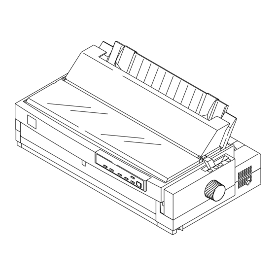
Page 11: Figure 1-1 Exterior View Of The Lq-2170
Product Description LQ-2170 Service Manual Figure 1-1 Exterior View of the LQ-2170 Rev.A... -
Page 12: Accessories
LQ-2170 Service Manual Product Description 1.1.2. Accessories Items included in the printer carton Table 1-1 Items Included with the Printer Enclosed Items Quantity User’s guide Driver diskette Ribbon cartridge Power cord Consumables Table 1-2 Consumables Consumable Item Part Number Ribbon cartridge... -
Page 13: Hardware Specifications
Product Description LQ-2170 Service Manual 1.2 Hardware Specifications This section provides detailed hardware specifications for the LQ-2170. 1.2.1 Printing Method Printing method Impact dot matrix Color Black Number of pins 24 pins Pin arrangement 12 2 staggered Pin diameter 0.21 mm (0.00083 inch) 0.353 mm... -
Page 14: Printing Specifications
LQ-2170 Service Manual Product Description 1.2.2 Printing Specifications Copy capability 1 original + 4 copies Print speed and printable columns Table 1-4 Print Speed and Printable Columns Print Speed (cps) Print Mode Character Pitch Printable Columns Normal Multipart High-speed draft... -
Page 15: Paper Handling Specifications
Product Description LQ-2170 Service Manual 1.2.3 Paper Handling Specifications Feeding method Friction feed (front, rear) Push tractor feed (front, rear) Push and pull feed (front, rear, bottom) Feeder Front push tractor, rear push tractor, CSF bin 1 /bin 2 (optional) -
Page 16: Table 1-7 Paper Thickness Lever Positions
LQ-2170 Service Manual Product Description Paper thickness lever Set the paper thickness lever to the appropriate position, as indicated in the following table. Table 1-7 Paper Thickness Lever Positions Paper Thickness ( inches) Paper Thickness (mm) Lever Position Minimum Maximum... -
Page 17: Paper Specifications
Product Description LQ-2170 Service Manual 4. Push-pull tractor feed Set the release lever to the REAR PUSH/FRONT PUSH position. Load paper from the front or rear entrance. Remove the paper eject assembly and attach the pull tractor unit. Remove any slack in the paper between the platen and pull tractor. -
Page 18: Figure 1-3 Printable Area For Cut Sheets
LQ-2170 Service Manual Product Description Printable area Figure 1-3 shows the printable area for cut sheets. The table below defines the abbreviations used in the figure. Table 1-10 Printable Area for Cut Sheets Abbreviations Single Sheet Multipart PW (width) Refer to Table 1-8. -
Page 19: Table 1-11 Specifications For Envelopes
Product Description LQ-2170 Service Manual Envelopes and Card Stock Paper/media specifications The following tables gives specifications for envelopes and card stock. Table 1-11 Specifications for Envelopes Front Entry Rear Entry Minimum Maximum Minimum Maximum No. 6 Width —- 166 mm (6.5") -
Page 20: Figure 1-4 Printable Area For Envelopes And Card Stock
LQ-2170 Service Manual Product Description Printable area The figure below shows the printable area for envelopes and card stock. Each abbreviation is defined in the following table. Table 1-13 Printable Area for Envelopes and Card Stock Abbreviations Envelopes Card Stock PW (width) Refer to Table 1-11. -
Page 21: Table 1-14 Specifications For Continuous Paper (Single Sheet And Multipart)
Product Description LQ-2170 Service Manual Continuous Paper Paper/media specifications The following table gives specifications continuous paper. Table 1-14 Specifications for Continuous Paper (Single Sheet and Multipart) Front Entry Rear Entry Bottom Entry Minimum Maximum Minimum Maximum Minimum Maximum Width 101 mm... -
Page 22: Figure 1-5 Printable Area For Continuous Paper
LQ-2170 Service Manual Product Description Printable area The figure below shows the printable area for continuous paper. Each abbreviation is defined in the following table. Table 1- 15 Printable Area for Continuous Paper Abbreviations Continuous Paper PW (width) Refer to Table 1-14. -
Page 23: Figure 1-6 Label Size
Product Description LQ-2170 Service Manual Continuous Paper with Labels Paper/media specifications The following table gives the specifications for continuous paper with labels. Table 1-16 Specifications for Continuous Paper with Labels Front Entry Rear Entry Bottom Entry Minimum Maximum Minimum Maximum... -
Page 24: Figure 1-7 Printable Area For Roll Paper
LQ-2170 Service Manual Product Description Roll Paper Note: Roll paper is not available in all models, and not available in the U.S. Paper/media specifications The following table shows specifications for roll paper. Table 1-17 Specifications for Roll Paper Front Entry... -
Page 25: Ribbon Specifications
Product Description LQ-2170 Service Manual 1.2.5 Ribbon Specifications Table 1-19 Statistics on the Ribbon Item Specification Type Fabric Color Black Ribbon life 8 million characters (draft, 10 cpi, 48 dots/ character) Dimension 506.0 mm (W) 123.5 mm (D) 23.0 mm (H) 19.92"... -
Page 26: Environmental Conditions
LQ-2170 Service Manual Product Description 1.2.7 Environmental Conditions Table 1-22 explains the conditions the printer requires during operation and when not operating. Table 1-22 Environmental Requirements Item Specifications Temperature 5 to 35 C/41 to 95 F ( operating 15 to 25 C/59 to 77 F (operating ä30 to 60 C/–22 to 140 F (non-operating) -
Page 27: Ce Marking
Product Description LQ-2170 Service Manual 1.2.10 CE Marking The following table lists CE marking information. Table 1-25 CE Marking Low Voltage Directive 73/23 / EEC EN60950 EMC Directive 89/336 / EEC EN55022 class B EN50082-1 , IEC801-2 IEC801-3 , IEC801-4... -
Page 28: Table 1-29 Environmental Conditions
LQ-2170 Service Manual Product Description Stacker capacity Table 1-28 Capacity of the Stacker CSF Bin 1 CSF Bin 2 Single sheets 140 sheets ( ——- 100 sheets ( Envelopes 15 sheets ( ——- 28 sheets ( Card stock 30 sheets ( ——-... -
Page 29: Table 1-30. Character Tables
Product Description LQ-2170 Service Manual 1.3 Firmware Specifications This section provides detailed information about LQ-2170 firmware. 1.3.1 Control Codes and Fonts Control codes ESC/P2 and IBM 2390/2391 plus emulations. Typefaces Bitmap fonts EPSON Draft 10 cpi, 12 cpi, 15 cpi... -
Page 30: Interface Specifications
LQ-2170 Service Manual Product Description 1.3.2 Interface Specifications This printer provides a bidirectional 8-bit parallel interface and a Type B optional interface slot, standard. 1.3.2.1 Parallel Interface (Forward Channel) Transmission mode 8-bit parallel, IEEE-P1284, compatibility mode Adaptable connector 57-30360 (Amphenol) or equivalent... -
Page 31: Figure 1-8 Data Transmission Timing
Product Description LQ-2170 Service Manual DATA data byte n+1 data byte n t h old STROBE tsetup tstb tnext BUSY tb u s y tready ACKNLG trep ly tack tn b u s y Figure 1-8 Data Transmission Timing Table 1-32 Maximum and Minimum Timings for Data Transmission... -
Page 32: Parallel Interface (Reverse Channel)
LQ-2170 Service Manual Product Description 1.3.2.2 Parallel Interface (Reverse Channel) Transmission mode IEEE-P1284 nibble mode Adaptable connector 57-30360 (Amphenol) or equivalent Synchronization Refer to the IEEE-P1284 Specification Handshaking Refer to the IEEE-P1284 Specification Signal level TTL-compatible (IEEE-P1284 level 1 device) -
Page 33: Interface Selection
[00 H][32 H] ..MFG: EPSON, CMD: ESCPL2-00, MDL: LQ-2170, CLS: PRINTER IBM 2391 Plus [00 H][33 H] ..MGF: EPSON, CMD: PRPXL24-01, MDL: LQ-2170, CLS: PRINTER 1.3.2.3 Interface Selection The printer has 2 interfaces: the parallel interface and Type B optional interface. These interfaces are selected manually in default setting mode or selected automatically. -
Page 34: Table 1-34. Paper Handling Sequence 1
LQ-2170 Service Manual Product Description 1.3.3 Paper Handling Sequence In this section, paper handling firmware sequences are described in several cases. Printer status Printer is on line (not in the pause state). No PE sensor detects that paper is loaded. -
Page 35: Table 1-36. Paper Handling Sequence 3
Product Description LQ-2170 Service Manual Printer status The front PE sensor detects that paper is loaded in the front paper path. The release lever is set to continuous paper Table 1-36 Paper Handling Sequence 3 Occurrence Result button pressed Printer goes off or on line. -
Page 36: Table 1-38. Paper Handling Sequence 5
LQ-2170 Service Manual Product Description Printer status The rear PE sensor detects that paper is loaded in the rear paper path. Release lever position is set to Friction. Table 1-38 Paper Handling Sequence 5 Occurrence Result button pressed Printer goes on or off line. -
Page 37: Paper Width Sensor Operation
Product Description LQ-2170 Service Manual 1.3.4. Paper Width (PW) Sensor Operation The PW sensor is mounted on the ribbon mask holder to measure the paper width and detect the top edge of the paper. However, in cases where print data is over the paper width, the image cut function does not operate in all modes. -
Page 38: Operating Instructions
LQ-2170 Service Manual Product Description 1.4 Operating Instructions This section provides detailed information about the LQ-2170 control panel buttons and LEDs. 1.4.1 Control Panel Operations The printer control panel contains 6 non-lock type push buttons and 10 LEDs for various printer functions. -
Page 39: Table 1-42. Operations At Power On
Product Description LQ-2170 Service Manual Operations at power on Turning the printer on while pressing panel buttons executes the functions below: Table 1-42 Operation at Power On Button Function LQ self-test Draft self-test Hexadecimal data dump Default setting Clear EEPROM... -
Page 40: Tear Off Function
LQ-2170 Service Manual Product Description 1.4.3 Micro Adjust Function The micro adjust function lets you set the TOF and tear off positions. After the printer is put in this mode, you can adjust the top of form (TOF) position up or down in increments of... -
Page 41: Self-Test Function
Product Description LQ-2170 Service Manual 1.4.5 Self-test Function Pressing the button while turning on the printer puts the printer in LQ self-test mode. Pressing button while turning on the printer puts the printer in Draft self-test mode. You can stop the self-test temporarily by pressing the button, and you can exit the self-test mode by turning off the printer. -
Page 42: Default Setting Function
LQ-2170 Service Manual Product Description 1.4.7 Default Setting Function Pressing the button while turning on the printer puts the printer in default setting mode. Some default printer settings can be changed in this operation. The method for setting defaults is described in the instruction sheets, which are printed out immediately after you enter the mode. -
Page 43: Bidirectional Adjustment Function
Product Description LQ-2170 Service Manual 1.4.9 Bidirectional Adjustment Function Pressing the button while turning on the printer puts the printer in bidirectional adjustment mode. In this mode, you can adjust the bidirectional alignment for the following three modes: 1. High-speed draft mode 2. -
Page 44: Main Components
LQ-2170 Service Manual Product Description 1.6 MAIN COMPONENTS The main components of the LQ-2170 are designed for easy removal and repair. main components are: C165 MAIN Board Assembly C165 PSB/PSE Board Assembly (120 V/230 V) C165 PNL Board Assembly Printer Mechanism Housing Assembly The following figure shows the main components of the LQ-2170. -
Page 45: C165 Main Board Assembly
Product Description LQ-2170 Service Manual 1.6.1 C165 MAIN Board Assembly The C165 MAIN board consists of a TMP96C141AF CPU, an E05B13 gate array, a program/CG ROM, a PS-RAM, an EEPROM, etc. IC11 PF Motor Driver IC3 P-ROM IC 5 PS RAM... -
Page 46: C165 Pnl Board Assembly
LQ-2170 Service Manual Product Description 1.6.3 C165 PNL Board Assembly This board function is the control panel for the LQ-2170. It consists of a power switch, six buttons, and 10 indicator LEDs. This board is almost same as it for the LQ-2170. -
Page 47: Housing Assembly
Product Description LQ-2170 Service Manual 1.6.5. Housing Assembly This consists of printer cover assembly, edge guide assembly, upper housing, lower housing assembly, etc. Figure 1-17 Housing Assembly 1-38 Rev.A... - Page 48 CHAPTER 2 Operating Principles Table of Contents 2.1 PRINTER MECHANISM OPERATION 2.1.1 Printing Mechanism ......... . 2-1 2.1.2 Carriage Movement Mechanism .
- Page 49 List of Figures Figure 2-1. Printhead Operation ........2-1 Figure 2-2.
-
Page 50: Printer Mechanism Operation
LQ-2170 Service Manual Operating Principles 2.1 PRINTER MECHANISM OPERATION This section describes the printer mechanism and explains how it works. 2.1.1 Printing Mechanism The printing mechanism is composed of the printhead, ink ribbon, and ribbon mask. The printhead is an 24-pin (12 pins 2) head for impact dot printing. -
Page 51: Carriage Movement Mechanism
Operating Principles LQ-2170 Service Manual 2.1.2 Carriage Movement Mechanism The carriage movement mechanism consists of the carriage assembly, carriage (CR) motor, timing belt, driven pulley, home position (HP) sensor, etc. The CR motor drives the timing belt. The carriage assembly is connected to the timing belt, which is moved by the CR motor. -
Page 52: Platen Gap Adjustment
LQ-2170 Service Manual Operating Principles 2.1.3 Platen Gap Adjustment You can adjust the platen gap (the gap between the platen and printhead) to allow the printer to use paper of different weights or thicknesses. When you move the platen gap adjust lever forward or backward, the carriage guide shaft rotates. -
Page 53: Paper Handling Mechanism
Operating Principles LQ-2170 Service Manual 2.1.4. Paper Handling Mechanisms During the normal operation, paper is fed to the printer, advanced to the specified position, and ejected from the printer. These paper-handling operations are performed by various paper handling mechanisms, such as tractors, platens, rollers, and gears. -
Page 54: Paper Advance Mechanism
LQ-2170 Service Manual Operating Principles 2.1.4.2. Paper Advance Mechanism This section describes how the friction and tractor advance mechanisms work to move the paper through the printer. 1. Friction Advance Method Paper is held between the platen and the paper guide rollers and between the paper tension roller and paper tension unit cover. - Page 55 Operating Principles LQ-2170 Service Manual 2. Push Tractor Method The push tractor method is used with the rear or front entrance. When the push tractor method is used with the rear entrance, the torque generated by the PF motor is transmitted to the push tractor gear through the PF motor pinion gear, paper advance reduction gear, and tractor reduction gear.
- Page 56 LQ-2170 Service Manual Operating Principles Figure 2-7. Push Tractor Operation Using the Front Paper Entrance Rev.A...
- Page 57 Operating Principles LQ-2170 Service Manual 3. Pull Tractor Method The pull tractor advances paper in basically the same way as the push tractor. The push tractor is installed at the paper entrance and pushes paper into the printer. On the other hand, the pull tractor is installed at the paper exit and pulls paper out of the printer mechanism.
- Page 58 LQ-2170 Service Manual Operating Principles 4. Push-Pull Tractor Method The push-pull tractor method is a combination of the push and pull tractor methods. Two tractors are used to advance the paper: one at the front paper entrance and the other at the rear paper entrance. They operate simultaneously to push and pull the paper through the printer mechanism.
- Page 59 Operating Principles LQ-2170 Service Manual Figure 2-10 Push-Pull Tractor Operation Using the Front Paper Entrance 2-10 Rev.A...
-
Page 60: Paper Paths
LQ-2170 Service Manual Operating Principles 2.1.5 Paper Paths This section describes various paper paths through the printer mechanism. These paper paths are divided into four groups, depending on which entrance (top, rear, bottom, or front) is used to feed paper. The printer has two PE (paper end) sensors. - Page 61 Operating Principles LQ-2170 Service Manual 2. Rear Entrance Figures 2-13, 2-14, and 2-15 show the paper paths for tractor feeding using the rear entrance. You can use the rear entrance with any of the following paper feed methods: push tractor feed, pull tractor feed, or push-pull tractor feed.
- Page 62 LQ-2170 Service Manual Operating Principles Figure 2-15. Push-Pull Tractor Feeding Using the Rear Entrance As shown above in Figure 2-15, when you use the pull tractor with this printer, you must remove the paper eject cover, which includes the paper tension roller, from the printer mechanism.
- Page 63 Operating Principles LQ-2170 Service Manual 4. Front Entrance Figures 2-17 through 2-20 show the paper paths for the front entrance. The front entrance can be used with any of the following paper feed methods: friction feed, push tractor feed, pull tractor feed, or push-pull tractor feed.
- Page 64 LQ-2170 Service Manual Operating Principles Down Figure 2-19 Pull Tractor Feeding Using the Front Entrance Figure 2-20 Push-Pull Tractor Feeding Using the Front Entrance Rev.A 2-15...
-
Page 65: Ribbon Advance Mechanism
Operating Principles LQ-2170 Service Manual 2.1.6 Ribbon Advance Mechanism The ribbon is held between the ribbon advance roller (ribbon driven gear) and the ribbon pressure roller. When the carriage moves from left to right and vice versa on the CR guide shaft, the timing belt turns the belt-driven pulley. -
Page 66: Power Supply Operation
LQ-2170 Service Manual Operating Principles 2.2 POWER SUPPLY OPERATION The printer can be powered by either of two power supply boards: the C165 PSB (120 V) or C165 PSE (230 V) power supply. These boards are the same for both the LQ-2170 and FX-2170. Additionally, the PSB and PSE boards function the same, except for a difference in primary circuitry. -
Page 67: Power Supply Circuit Operation
Operating Principles LQ-2170 Service Manual 2.2.2 Power Supply Circuit Operation The power supply circuit is composed of an RCC (ringing choke converter) system and the power switch circuit in the secondary circuitry. The power supply circuit has several protection and control circuits. This section describes these circuits. - Page 68 LQ-2170 Service Manual Operating Principles 3. +35 V Constant Voltage Control Circuit The +35 V constant voltage control circuit is illustrated below. +35V Line ZD51 ZD81 ZD82 ZD83 ZD84 ZD85 GND Line Figure 2-25 +35 V Line Constant Voltage Control Circuit The constant voltage control circuit operates to keep the 35 V line at 35 V 6 %.
- Page 69 Operating Principles LQ-2170 Service Manual 5. +35 V Line Over Current Protection Circuit The +35 V line over current control circuit is illustrated below. +35V Line Figure 2-27 +35 V Line Over Current Protection Circuit When the +35 V line becomes less than 27 V, Q82 and Q54 turn on, and PC1 turns on. Consequently, Q32 and Q31 turn off, and then switching FET Q1 shuts off.
- Page 70 LQ-2170 Service Manual Operating Principles 7. +5 V Line Constant Voltage Control Circuit The +5 V line constant voltage control circuit is shown below. +35V R 5 3 +5v Line ZD55 R 6 5 G N D IC51 TL494CN Figure 2-29 +5 V Line Constant Voltage Control Circuit Port 16 of IC51 (TL494CN) monitors the + 5 V line, and the voltage is compared with the standard voltage, which is input into port 15.
-
Page 71: Control Circuit
Operating Principles LQ-2170 Service Manual 2.3 CONTROL CIRCUIT The control circuit consists of the C165 MAIN board assembly and C165 PNL board This section describes the major components and explains how the boards work. 2.3.1 Overview of Control Circuit Operation The printer’s control circuit includes a TMP96C141AF CPU that runs at 17.20 MHz, an E05B13YA gate... - Page 72 LQ-2170 Service Manual Operating Principles The following figure shows the data flow from the host computer to the printhead. Data sent from the host computer is converted to image data and transmitted to the printhead through the gate array. TMP96C041AF...
-
Page 73: System Reset Circuit
Operating Principles LQ-2170 Service Manual 2.3.2 System Reset Circuit Control circuits IC1 and IC2 are initialized when a RESET signal (LOW level) is output from port 1 (VOUT) of IC10. IC10 monitors the +5 V line on port 3, and resets under the following conditions:... -
Page 74: Cr Motor Driver Circuit
LQ-2170 Service Manual Operating Principles 2.3.4 CR Motor Driver Circuit The CR motor driver circuit is shown below. PG00 IN A PG01 IN-A CR A PG02 IN B PG03 CR-A IN-B Address CR B Data Line CR-B CRI0 C29, 30... -
Page 75: Pf Motor Driver Circuit
Operating Principles LQ-2170 Service Manual 2.3.5 PF Motor Driver Circuit The figure below shows the PF motor driver circuit. 74LS32 PFI1 PF A PFI2 PF-A Gate Array PF B VREF1 HOLD 66 VREF2 PF-B IC11 UDN2917EB Figure 2-36 PF Motor Driver Circuit The gate array receives phase data from the CPU via ports 5 (PG10), 6 (PG11), 7 (PG12), and 8 (PG13), converts the data to UDN2917 form, and then sends that phase data to ports 43 (PH1) and 26 (PH2). -
Page 76: Sensor Circuits
LQ-2170 Service Manual Operating Principles 2.3.7 Sensor Circuits The CPU detects conditions of the following sensors: home position (HP) sensor, release sensors 1 and 2, platen gap (PG) sensor, rear and front paper end (PE) sensors, paper width (PW) sensor, and cover open sensor. - Page 77 CHAPTER 3 Disassembly and Assembly Table of Contents 3.1 OVERVIEW 3.1.1 Precautions..........3-1 3.1.2 Tools .
- Page 78 List of Figures Figure 3-1. Screw Types and Abbreviations ......3-3 Figure 3-2. Flowchart for Disassembling the Printer ..... . 3-4 Figure 3-3.
- Page 79 Figure 3-49. Removing the Right CSF Cover......3-31 Figure 3-50. Engaging 5 Gears ........3-31 Figure 3-51.
-
Page 81: Overview
LQ-2170 Service Manual Disassembly and Assembly 3.1 OVERVIEW This section describes various points to note when disassembling and assembling the printer. 3.1.1 Precautions Follow the precautions below for disassembly or assembly. Before disassembling, assembling, or adjusting the printer, disconnect the power supply cable from the AC power socket. -
Page 82: Service Checks After Repair
Disassembly and Assembly LQ-2170 Service Manual 3.1.3 Service Checks After Repair Before returning the printer after service, use the check list in Table 3-3, which provides a record to make servicing and shipping more efficient. Table 3-3. Inspection Check List for the Repaired Printer... -
Page 83: Specifications For Screws
LQ-2170 Service Manual Disassembly and Assembly 3.1.4 Specifications for Screws Table 3-4 lists the abbreviations used in the following sections for small parts, such as screws and washers. Table 3-4. Screw Types and Abbreviations Abbreviation Part Name Cross-recessed pan head S-tight screw... -
Page 84: Printer Disassembly And Assembly
Disassembly and Assembly LQ-2170 Service Manual 3.2. PRINTER DISASSEMBLY AND ASSEMBLY This section describes procedures for disassembling and assembling the main components of the printer. When the procedure for installing a component is simply the reverse of removing the component, this chapter does not describe the assembly procedure. -
Page 85: Before Starting Disassembly Procedures
LQ-2170 Service Manual Disassembly and Assembly 3.2.1. Before Starting Disassembly Procedures 1. Remove the following parts: Front edge guide assembly Front cover Bottom cover Rear edge guide assembly Printer cover Paper eject assembly Front/rear tractor assembly Ribbon cartridge Refer to the following figure. -
Page 86: Removing The Panel Board Assembly
Disassembly and Assembly LQ-2170 Service Manual 3.2.2. Removing the Panel Board Assembly Remove the printer cover and ribbon cartridge (see Section 3.2.1). Release the left clips for the panel board assembly by pushing them from the cutout located on the inside front of the upper housing assembly. -
Page 87: Removing The Printhead
LQ-2170 Service Manual Disassembly and Assembly 3.2.3. Removing the Printhead Remove the printer cover and ribbon cartridge (see Section 3.2.1). Remove 2 CBS screws (3 10, F/Zn) securing the printhead to the CR assembly. Remove the printhead from the CR assembly. -
Page 88: Removing The Hp Sensor
Disassembly and Assembly LQ-2170 Service Manual 3.2.4 Removing the HP Sensor Remove the printer cover, ribbon cartridge, front edge guide, and front cover (see Section 3.2.1). Disconnect the connector cable for the HP sensor. Remove the HP sensor by pushing up and releasing the 2 clips at the bottom of the HP sensor from the front paper entrance. - Page 89 LQ-2170 Service Manual Disassembly and Assembly Mount the onto the ribbon mask holder groove, aligning the bottom line of PW sensor assembly micro photo sensor to the bottom line of the groove. Whenever you remove the PW sensor assembly, clean the surface of the sensor by wiping it with a soft material.
-
Page 90: Removing The Platen Assembly
Disassembly and Assembly LQ-2170 Service Manual 3.2.6 Removing the Platen Assembly Remove the printer cover, ribbon cartridge, and platen knob (see Section 3.2.1). Release both locks for the left and right bushings (8 mm) by pushing the lever holder for the bushings outside, and then pulling the holder lever forward. -
Page 91: Removing The Upper Housing Assembly
LQ-2170 Service Manual Disassembly and Assembly 3.2.7 Removing the Upper Housing Assembly Remove the rear edge guide assembly, paper eject assembly, rear tractor unit, and printer cover (see Section 3.2.1). Remove the panel board assembly (see Section 3.2.2). Remove 4 CBB screws (4 14, F/Zn) securing the upper housing assembly. -
Page 92: Removing The Case Open Sensor Assembly
Disassembly and Assembly LQ-2170 Service Manual 3.2.8 Removing the Case Open Sensor Assembly Remove the rear edge guide assembly, paper eject assembly, rear tractor unit, and printer cover (see Section 3.2.1). Remove the panel board (see Section 3.2.2) and upper housing assemblies (see Section 3.2.7). -
Page 93: Removing The Printer Mechanism
LQ-2170 Service Manual Disassembly and Assembly 3.2.10 Removing the Printer Mechanism Remove the rear/front edge guide assembly, front cover, paper eject assembly, rear/front tractor units, and printer cover (see Section 3.2.1). Remove the panel board assembly (see Section 3.2.2) and upper housing assembly (see Section 3.2.7). - Page 94 Disassembly and Assembly LQ-2170 Service Manual 3.2.10.1 Removing the PF Motor Remove the rear/front edge guide assembly, front cover, paper eject assembly, rear/front tractor unit, and printer cover (see Section 3.2.1). Remove the panel board (see Section 3.2.2) and upper housing assemblies (see Section 3.2.7).
-
Page 95: Removing The Pg Sensor Assembly
LQ-2170 Service Manual Disassembly and Assembly 3.2.10.2 Removing the PG Sensor Assembly Remove the rear/front edge guide assembly, front cover, paper eject assembly, rear/front tractor unit, and printer cover (see Section 3.2.1). Remove the panel board (see Section 3.2.2) and upper housing assemblies (see Section 3.2.7). -
Page 96: Removing The Right Frame Assembly
Disassembly and Assembly LQ-2170 Service Manual 3.2.10.3 Removing the Right Frame Assembly Remove the rear/front edge guide assembly, front cover, paper eject assembly, rear/front tractor unit, and printer cover (see Section 3.2.1). Remove the panel board (see Section 3.2.2) and upper housing assemblies (see Section 3.2.7). - Page 97 LQ-2170 Service Manual Disassembly and Assembly Remove the right sub frame from the right frame assembly. Remove the following 11 parts from the right frame assembly. 2 compression springs (200 g) 2 plain washers 1 spur gear (27 mm) 2 spur gears (34.5 mm) 1 spur gear (34 mm) 1 spur gear (21 mm) 1 combination gear (8 mm, 31.5 mm)
- Page 98 Disassembly and Assembly LQ-2170 Service Manual When you engage the release lever and release lever transmission to the tractor clutch cam, notice the points in the following figure. The tightening torque for the CBS screws (3 6, F/Zn) and (3 8, F/Zn) 0.78 ~ 0.98 N.m (8 ~ 10 Kg - cm)
-
Page 99: Removing The Left Frame Assembly
LQ-2170 Service Manual Disassembly and Assembly 3.2.10.5 Removing the Left Frame Assembly Remove the rear/front edge guide assembly, front cover, paper eject assembly, rear/front tractor unit, and printer cover (see Section 3.2.1). Remove the panel board assembly (see Section 3.2.2), upper housing assembly (see Section 3.2.7), and then remove the printer mechanism (see Section 3.2.10 ). -
Page 100: Removing The Ribbon Drive (Rd) Assembly
Disassembly and Assembly LQ-2170 Service Manual 3.2.10.6 Removing the Ribbon Drive (RD) Assembly Remove the rear/front edge guide assembly, front cover, paper eject assembly, rear/front tractor unit, and printer cover (see Section 3.2.1). Remove the panel board (see Section 3.2.2) and upper housing assemblies (see Section 3.2.7). -
Page 101: Removing The Cr Assembly
LQ-2170 Service Manual Disassembly and Assembly 3.2.10.7 Removing the CR Assembly Remove the rear/front edge guide assembly, front cover, paper eject assembly, rear/front tractor unit , and printer cover. Remove the panel board (see Section 3.2.2) and upper housing assemblies (see Section 3.2.7) . - Page 102 Disassembly and Assembly LQ-2170 Service Manual Insert the timing belt properly into the 2 holding slots at the bottom of the CR assembly. Take up the timing belt slack between the two slots completely, as shown in the following figure.
-
Page 103: Removing The Rear Pe Sensor Assembly
LQ-2170 Service Manual Disassembly and Assembly 3.2.10.8 Removing the Rear PE Sensor Assembly Remove the rear/front edge guide assembly, front cover, paper eject assembly, rear/front tractor unit, and printer cover. Remove the panel board (see Section 3.2.2) and upper housing assemblies (see Section 3.2.7). -
Page 104: Removing The C165 Main Board Assembly
Disassembly and Assembly LQ-2170 Service Manual 3.2.11 Removing the C165 MAIN Board Assembly Remove the rear/front edge guide assembly, front cover, paper eject assembly, rear/front tractor unit, and printer cover (see Section 3.2.1) Remove the panel board (see Section 3.2.2) and upper housing assemblies (see Section 3.2.7). -
Page 105: Removing The C165 Psb/E Board Assembly
LQ-2170 Service Manual Disassembly and Assembly 3.2.12 Removing the C165 PSB/E Board Assembly Remove the rear/front edge guide assembly, front cover, paper eject assembly, rear/front tractor unit, and printer cover. Remove the panel board (see Section 3.2.2) and upper housing assemblies (see Section 3.2.7). -
Page 106: Disassembly And Assembly Of Csf Bin
Disassembly and Assembly LQ-2170 Service Manual 3.3. Disassembly and Assembly of CSF Bin 1 This section describes procedures for disassembling and assembling the optional cut sheet feeder. In general, you can install a component in the CSF simply by reversing the procedure for removing it. - Page 107 LQ-2170 Service Manual Disassembly and Assembly Be careful of the cable alignment for the CN1 connector cable and earth cables. Align those cables as shown in the following figure. If these cables is not aligned properly, the CSF gear cover cannot be assembled properly.
- Page 108 Disassembly and Assembly LQ-2170 Service Manual 3.3.2 Disassembling Paper Support Block Assembly Remove the CSF gear cover. Refer to step 1 in Section 3.3.1. Remove the stepping motor. Refer to steps 2 and 3 in the Section 3.3.1. Remove the E-ring fixing the right edge of the paper feed shaft.
- Page 109 LQ-2170 Service Manual Disassembly and Assembly Remove the paper support assembly along with the paper support shaft and paper shaft holder by pulling upward. Figure 3-45 Removing the Paper Support Block Assembly Remove both paper feed rollers from both paper support assemblies.
- Page 110 Disassembly and Assembly LQ-2170 Service Manual 3.3.3 Removing the Paper Eject Assembly Cover Remove the paper eject assembly cover by releasing 2 clips located along both edges of the paper eject assembly cover, as shown in the following figure. Cover, Paper Eject Assy.,...
- Page 111 LQ-2170 Service Manual Disassembly and Assembly 3.4 Disassembly and Assembly of CSF Bin 2 3.4.1 Disassembling the Right Side Block Remove the gear train cover by releasing the 4 clips shown in the following figure. Gear Train Cover Figure 3-49 Removing the Gear Train Cover Remove the following 5 gears and 1 spring from the right CSF frame.
-
Page 112: Disassembling The Paper Support Block Assembly
Disassembly and Assembly LQ-2170 Service Manual 3.4.2 Disassembling the Paper Support Block Assembly Remove 1 E -ring fixing the paper feed roller shaft to the right CSF frame. Remove 2 CTBS (3 8) screws securing the paper support shaft to both right and left CSF frames. - Page 113 CHAPTER 4 Adjustments Table of Contents 4.1 ADJUSTMENT OVERVIEW 4.1.1 Required Adjustments ........4-1 4.1.2.
-
Page 114: Adjustment Overview
LQ-2170 Service Manual Adjustment 4.1 ADJUSTMENT OVERVIEW 4.1.1 Required Adjustments This section describes what adjustments are required after any part is removed or replaced. The following table shows the relationship between the repaired item and the adjustment. Table 4-1 Required Adjustments... -
Page 115: Adjusting And Resetting The Printer
Adjustment LQ-2170 Service Manual 4.2 ADJUSTING AND RESETTING THE PRINTER 4.2.1 Platen Gap Adjustment If you have rotated or reassembled the rear CR guide shaft or parallelism adjustment bushing, or if printing is light or dark, even at the proper PG lever position, perform this adjustment at 3 positions: the 5th, 80th, and 130th columns. - Page 116 LQ-2170 Service Manual Adjustment Insert a thin screwdriver into the drilled hole, located at the right edge of the rear CR guide shaft and adjust the platen gap by moving the screwdriver to forward or backward until the gap is large enough for a 0.36 mm thickness gauge but too narrow for a 0.40 mm thickness gauge.
- Page 117 Adjustment LQ-2170 Service Manual 4.2.2 Bidirectional Print Alignment Adjustment This section describes the procedure for adjusting the bidirectional print alignment, required after mechanism repair. This procedure is also necessary if you replace the main board assembly or EEPROM, because the adjusted value is written to the EEPROM on the C165 MAIN board. You can perform the adjustment from the Settings Diskette, using the control panel, or with a remote utility.
- Page 118 LQ-2170 Service Manual Adjustment < Bi-d adjustment > > Mode 0 = 0 Mode 1 = 0 Mode 2 = 0 Cancel Print Speed Value Write Default [ ESC ] [ SPACE ] [ RET ] [ HOME ] Figure 4-8 Bi-d Adjustment Menu...
- Page 119 Adjustment LQ-2170 Service Manual 4.2.2.2 Bi-d Print Alignment Adjustment from the Control Panel Turn the printer on while pressing the PAUSE button to put the printer into Bi-D adjustment mode. The printer prints out a guide sheet, containing 25 patterns in Super Draft mode.
-
Page 120: Factory Settings
LQ-2170 Service Manual Adjustment 4.2.3 Factory Settings This section describes the procedure to reset factory settings, which is necessary if the main board or EEPROM is replaced. You can perform this procedure only with the Settings Diskette. Notes: After you select factory settings in the Setting File menu, be sure to run the check program in the Main Menu. -
Page 121: Tpe Level Reset
Adjustment LQ-2170 Service Manual 4.2.4 TPE Level Reset This section describes the procedure to reset the TPE (top paper end) level. This operation is required when the PW sensor assembly is replaced, and if it is not performed, the printer does not recognize that the PW sensor has been replaced, thus, limiting the ability of the new sensor to operate. - Page 122 CHAPTER 5 Troubleshooting Table of Contents 5.1 OVERVIEW 5.2 TROUBLESHOOTING INFORMATION 5.2.1 PRINTHEAD ..........5-1 5.2.2 SENSORS .
-
Page 123: Troubleshooting
LQ-2170 Service Manual Troubleshooting 5.1 OVERVIEW This chapter contains flowcharts and checkpoint tables to help you troubleshoot the printer. Flowcharts let you isolate a faulty unit based on abnormal symptoms. The checkpoint tables let you identify the faulty part or unit by checking the values or ranges listed for each component. -
Page 124: Sensors
Troubleshooting LQ-2170 Service Manual 5.2.2 Sensors Table 5-2 Sensor Test Points Sensor Test Method Test Pin Connector Meter Reading Number (Set Meter to DC Voltage. ) Number Place one lead on pin 1 and the other Open: +5 V lead on pin 2, and check the voltage while... -
Page 125: Motors
LQ-2170 Service Manual Troubleshooting 5.2.3 Motors Table 5-3 Motor Test Points Test Method Motor Common Test Pin Connector (Set Meter to Ohms. Disconnect Meter Reading Number Number Motor from Main Board after the Number Printer is Powered off.) CR Motor... -
Page 126: Unit Level Troubleshooting
Troubleshooting LQ-2170 Service Manual 5.3 UNIT LEVEL TROUBLESHOOTING You may be able to identify the defective unit just from the symptom displayed. The table below provides the symptoms for a number of failures. Once you identify the problem, refer to the flowchart listed in the right-hand column of the table below to determine the cause of the problem. - Page 127 LQ-2170 Service Manual Troubleshooting 1. Abnormal CR Operation Rev.A...
- Page 128 Troubleshooting LQ-2170 Service Manual 2. Abnormal Paper Feed Operation 1 START When Is CN11 the printer is Connect connected powered on, does CN11 correctly? the CR motor correctly. rotate? Check the resistance Is the of the motor coils. problem See Table 5-3.
- Page 129 LQ-2170 Service Manual Troubleshooting 2. Abnormal Paper Feed Operation 2-1 START Does CN10 Connect it the PF motor connected correctly. rotate? correctly? Is the problem When corrected? the printer is powered on, is Go to flowchart paper ejected 2-1. automatically?
- Page 130 Troubleshooting LQ-2170 Service Manual 3. Abnormal Control Panel Operation Continued from flowchart 2. cut-sheet When paper loaded paper is loaded, correctly, but continuous is it ejected paper not loaded automatically? at all? Connect CN7 connected correctly. correctly? CN12 Connect CN12 connected correctly.
-
Page 131: Abnormal Printing
LQ-2170 Service Manual Troubleshooting 4. Abnormal Printing START Does Check the Operate button the Operate button on the control panel using turn power on a multimeter. and off? Replace the Do the Operate button PNL board. Check them using control panel a multimeter. -
Page 132: Repairing The C165Psb/Pse Board Assembly
Troubleshooting LQ-2170 Service Manual 5.4 REPAIRING C165 PSB/PSE BOARD ASSEMBLY This section provides instructions to repair a defective power supply board assembly. It describes various symptoms, likely causes, and checkpoints. Checkpoints refer to proper waveforms, resistances, and other values to check when evaluating the operation of any potentially faulty component. Check these values and take the appropriate action. - Page 133 LQ-2170 Service Manual Troubleshooting Table 5-6. Repairing the C165 PSB/PSE Board Assembly (Continued) Cause Checkpoint Solution Problem The 35 V and Q32 is dead. Check that the resistance between the Replace 5 V lines are collector and emitter is infinite.
-
Page 134: Repairing The C165 Main Board Assembly
Troubleshooting LQ-2170 Service Manual 5.5 REPAIRING THE C165 MAIN BOARD ASSEMBLY This section provides instructions to repair the C165 MAIN board assembly. It describes various problems, symptoms, likely causes, and solutions. The checkpoint column provides proper waveforms, resistance values, and other information for each component of C165 MAIN. - Page 135 LQ-2170 Service Manual Troubleshooting Table 5-7. Repairing the C165 MAIN Board Assembly Problem Cause Checkpoint Solution Check the oscillator signal at pins 26 If the signal is not or 27 of the CRU1 correct, replace IC1 ( or replace the main board).
- Page 136 Troubleshooting LQ-2170 Service Manual Table 5-7. Repairing the C165 MAIN Board Assembly Cause Solution Problem Checkpoint IC1 is defective. IC2 is Check input signal waveform at pins 43 If the input signal defective. IC11 is and 26 of IC11. is not correct, defective.
-
Page 137: Repairing The Printer Mechanism
LQ-2170 Service Manual Troubleshooting 5.6 REPAIRING THE PRINTER MECHANISM This section provides instructions for repairing the printer mechanism. It describes various problems, symptom, likely causes, checkpoints, and solutions. The checkpoint column shows items to be checked, including proper values to be set for each component of the printer mechanism. For replacement and adjustment instructions, see Chapter 3, Disassembly and Assembly, and Chapter 4, Adjustments. - Page 138 Troubleshooting LQ-2170 Service Manual Table 5-8. Repairing the Printer Mechanism Problem Symptom Cause Checkpoint Solution A foreign object Check the HP Remove the any is jammed sensor. foreign object. CR operation is between both abnormal. The CR moves terminals of the slightly and then HP sensor.
- Page 139 LQ-2170 Service Manual Troubleshooting Table 5-8. Repairing the Printer Mechanism Problem Symptom Cause Checkpoint Solution CN10 is Check CN10. Connect CN10 Abnormal disconnected correctly. paper feed from the main board. The rear or front Check the Replace the rear PE sensor is...
- Page 140 Troubleshooting LQ-2170 Service Manual Table 5-8. Repairing the Printer Mechanism Problem Symptom Cause Checkpoint Solution CN12 is not Check the Connect the Paper feed is connected connector. Refer CN12 correctly. abnormal. Cut-sheet paper correctly. to page 3-19. is loaded correctly, but...
- Page 141 LQ-2170 Service Manual Troubleshooting Rev.A 5-19...
- Page 142 CHAPTER 6 Maintenance Table of Contents 6.1 PREVENTIVE MAINTENANCE 6.2 APPLYING LUBRICATION List of Figures Figure 6-1. Lubrication Points 1 and 3 ....... . . 6-2 Figure 6-2.
-
Page 143: Preventive Maintenance
6.2 APPLYING LUBRICATION EPSON recommends the printer be lubricated at the points illustrated in Figure 6-1. Table 6-2 lists each point along with its recommended lubricant. The recommended lubricants are EPSON G-26 and O-2, which have been tested extensively and found to comply with the needs of this printer. (Table 6-1 provides details about these lubricants.) Before applying a lubricant, be sure the surface to be lubricated is clean. -
Page 144: Figure 6-1. Lubrication Points 1 And
Maintenance LQ-2170 Service Manual Cam, Clutch, Tractor Spur Gear, 34.5 : Lubrication Point Ref. No.(1) : Lubrication Point Ref. No.(3) Figure 6-1. Lubrication Points 1 and 3 Gap Adjust Lever Platen Gap Adjustment Slot Lubricate all these slots Lubrication Point Ref. No. (2) Figure 6-2. -
Page 145: Figure 6-3. Lubrication Point
LQ-2170 Service Manual Maintenance : Lubrication Point Ref. No. 4 Figure 6-3. Lubrication Point 4 : Lubrication Point Ref. No.(5) : Lubrication Point Ref. No.(6) : Lubrication Point Ref. No.(7) Figure 6-4. Lubrication Points 5, 6, and 7 Rev. A... - Page 146 Appendix Table of Contents A.1. EXPANDED PRODUCTION COMMANDS A.2. EEPROM ADRESS MAP A.3 CONNECTOR SUMMARY A.4 CIRCUIT DIAGRAMS A-11 A.5 CIRCUIT BOARD COMPONENT LAYOUTS A-17 A.6 EXPLODED DIAGRAMS A-20 List of Figures Figure A-1. Cable Connections ........A-5 Figure A-2.
-
Page 147: Expanded Production Commands
LQ-2170 Service Manual Appendix A.1 EXPANDED PRODUCTION COMMANDS 1. Write Bidirectional Adjustment Data to EEPROM Format 1B 7C 00 06 00 00 FF 00 (in hex) dl d2 d3 Parameters Print speed (0: High speed draft /Draft, 1: Draft copy 2: LQ) -
Page 148: Eeprom Adress Map
Appendix LQ-2170 Service Manual A.2 EEPROM ADDRESS MAP Address Data Data Format Default 00H, 01H Reserved 0000H Area 1 02H, 03H Character table 0000H 0: PC437 1: PC850 2: PC860 selection (PC437) 3: PC863 4: PC865 5: PC861 6: BRASCII... - Page 149 LQ-2170 Service Manual Appendix Address Data Data Format Default Reserved 0000H Pitch direction 0: Bi-d, 1: Uni-d setting I/F mode selection 0: Auto I/F Selection, 1: Parallel I/F, 2: Type-B (Auto) Auto I/F wait time 10: 10 Sec., 30: 30 Sec., 00: 10 Sec.
- Page 150 Appendix LQ-2170 Service Manual Address Data Data Format Default Manual feed wait 3 to 30 (in units of 0.1 sec.), 00H: 0.3 sec. time (same as default) (0.3 sec.) 2CH 1 Tear-off wait time 3 to 30 (in units of 0.1 sec.) , 00H: 0.3 sec.
-
Page 151: Figure 1-16. Printer Mechanism
LQ-2170 Service Manual Appendix A.3 CONNECTOR SUMMARY Figure A-1 illustrates how primary components are connected. Table A-1 summarizes functions and sizes of the connectors. Printer Mechanism PF Motor CR Motor PG Sensor Board Assy., C166 PSB / PSE Release Lever Position Sensor... - Page 152 Appendix LQ-2170 Service Manual Table A-1. Connector Summary Board Connector Function Pins Parallel interface Type B interface C165 PSB/PSE board assembly HP sensor Rear PE sensor Front PE sensor PW sensor MAIN Board Printhead Assembly Printhead CN10 PF motor CN11...
- Page 153 LQ-2170 Service Manual Appendix Table A-5. Connector Pin Assignments – CN6 Signal Name Function Front paper end signal —- Signal GND Table A-6. Connector Pin Assignments - CN7 Signal Name Function TOP paper end signal —- Signal GND —- +5 VDC line —-...
- Page 154 Appendix LQ-2170 Service Manual Table A-8. Connector Pin Assignments – CN9 Signal Name Function Head data 3 HD11 Head data 11 HD19 Head data 19 —- +35V +35 VDC line Head data 2 —- +35V +35 VDC line Head data 7...
- Page 155 LQ-2170 Service Manual Appendix Table A-13 Connector Pin Assignments – CN14 Signal Name Function CSF motor phase A CSF motor phase B –A CSF motor phase –A –B CSF motor phase –B HOLD CSF motor hold signal —- +5 VDC line —-...
- Page 156 Appendix LQ-2170 Service Manual A-10 Rev.A...
-
Page 157: Circuit Diagrams
LQ-2170 Service Manual Appendix A.4 CIRCUIT DIAGRAMS Figure A-2. C165 MAIN Board Assembly Circuit Diagram Rev. A A-11... - Page 158 Appendix LQ-2170 Service Manual A-12 Rev.A...
- Page 159 LQ-2170 Service Manual Appendix Figure A-3. C165 PSB Board Assembly Circuit Diagram Rev. A A-13...
- Page 160 Appendix LQ-2170 Service Manual A-14 Rev.A...
- Page 161 LQ-2170 Service Manual Appendix Figure A-4. C165 PSE Board Assembly Circuit Diagram Rev. A A-15...
- Page 162 Appendix LQ-2170 Service Manual A-16 Rev.A...
-
Page 163: Circuit Board Component Layouts
LQ-2170 Service Manual Appendix A.5 CIRCUIT BOARD COMPONENT LAYOUTS Figure A-5. C165 MAIN Baord Assembly Component Layout Rev. A A-17... - Page 164 Appendix LQ-2170 Service Manual Figure A-6. C165 PSB Board Assembly Component Layout A-18 Rev.A...
- Page 165 LQ-2170 Service Manual Appendix Figure A-7 C165 PSE Board Assembly Component Layout Rev. A A-19...
-
Page 166: Exploded Diagrams
Appendix LQ-2170 Service Manual A.6 EXPLODED DIAGRAMS Figure A-8. LQ-2170 Exploded Diagrams (1) A-20 Rev.A... - Page 167 LQ-2170 Service Manual Appendix Figure A-9. LQ-2170 Exploded Diagrams (2) Rev. A A-21...
- Page 168 Appendix LQ-2170 Service Manual Figure A-10. LQ-2170 Exploded Diagrams (3) A-22 Rev.A...
- Page 169 LQ-2170 Service Manual Appendix Figure A-11. C.S.F. Bin1 Exploded Diagrams (1) Rev. A A-23...
- Page 170 Appendix LQ-2170 Service Manual Figure A-12. C.S.F. Bin1 Exploded Diagrams (2) A-24 Rev.A...
- Page 171 LQ-2170 Service Manual Appendix Figure A-13. C.S.F. Bin2 Exploded Diagrams Rev. A A-25...
- Page 172 Appendix LQ-2170 Service Manual Table A-15 Part No. Reference Table A-26 Rev.A...
- Page 173 LQ-2170 Service Manual Appendix Table A-15 Part No. Reerence Table (Continue) Rev. A A-27...
- Page 174 Appendix LQ-2170 Service Manual A-28 Rev.A...
- Page 175 EPSON Printed in Japan...
Need help?
Do you have a question about the LQ-2170 and is the answer not in the manual?
Questions and answers