Advertisement
A
T
D D E N D U M
O
A n em om et er Tr an s m it te r K i t
In s ta l l at i on M a nu a l
Changes Covered In This Addendum
• New instructions to disconnect anemometer cable from newer versions of
the ISS that have an external housing for the sensor interface module.
• Anemometer sensor cable connection changed slightly because of new
sensor interface module in the transmitter kit.
Unplugging the Anemometer Cable from the ISS
The instruction manual for the Anemometer Transmitter Kit includes instruc-
tions for disconnecting the anemometer cable from early versions of the ISS.
Early ISS's have the sensor interface module (SIM) mounted inside the radiation
shield. Use the instructions in this addendum to disconnect the anemometer
cable from later versions ISS that have the SIM mounted in an external housing
beneath the radiation shield.
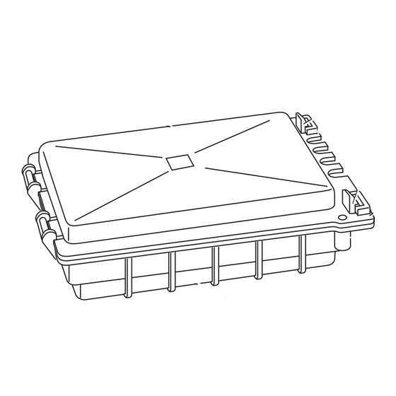
1. Locate the SIM housing on the bottom of the ISS radiation shield.
2. Push back on the two plastic latches to release the cover, then open the cover.
You should now be able to see the SIM.
SIM Housing Cover
3. Locate the anemometer cable, labeled WIND, and disconnect it from the ISS
sensor interface module.
© Davis Instruments Corp. 2003. All rights reserved.
:
SIM Housing
Opening the SIM Housing Cover
( 510 ) 732-9229 • FAX ( 510 ) 732-9188 • sales@davisnet.com • www.davisnet.com
1
Use your thumbs to push
back on the two (2) plastic
latches.
2
With the latches pushed
back, use your fingers to
lift up on the corner edges
of the cover.
Screw Fastening Holes.
Use self-threading screws:
#6 x 0.5" (3.5mm x 12 mm)
3465 Diablo Ave., Hayward, CA 94545-2778
07395.137A (Rev A, March 31, 2003)
Product #6330
Advertisement
Table of Contents

Related Manuals for DAVIS 6330


Summary of Contents for DAVIS 6330
- Page 1 3. Locate the anemometer cable, labeled WIND, and disconnect it from the ISS sensor interface module. 3465 Diablo Ave., Hayward, CA 94545-2778 ( 510 ) 732-9229 • FAX ( 510 ) 732-9188 • sales@davisnet.com • www.davisnet.com © Davis Instruments Corp. 2003. All rights reserved. 07395.137A (Rev A, March 31, 2003)
- Page 2 Anemometer Transmitter Kit Connections Please refer to the following illustration when you are connecting the anemome- ter cable to the transmitter kit. Instructions for connecting the anemometer are located in the “Preparing the Anemometer Transmitter” section in the Anemom- eter Transmitter Kit Installation Manual. 3-Volt Lithium Battery Transmitter ID Switches...
Need help?
Do you have a question about the 6330 and is the answer not in the manual?
Questions and answers