Table of Contents
Advertisement
Quick Links
The Integrated Sensor Suite (ISS) collects several types of weather readings
for display at your Vantage Pro
through a cable or by wireless transmission, depending on the version.
With Wireless Vantage Pro
one of eight sensor stations transmitting to your console/receiver(s). See
"Additional Mounting Options" and "Appendix A: Wireless Transmitter IDs".
The Integrated Sensor Suite for Vantage Pro
Wind Speed
Wind Direction
Rainfall
Outside Temperature
Outside Humidity
The Integrated Sensor Suite for Vantage Pro Plus
Ultraviolet Radiation (UV)
Solar Radiation
Note: To upgrade a Vantage Pro system to Vantage Pro Plus, see "Appendix B: Optional Accessories".
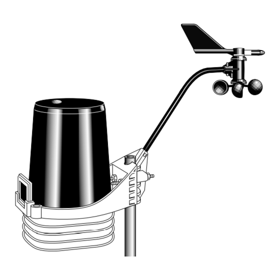
For mounting purposes, the Integrated Sensor Suite (ISS) consists of two sides:
the anemometer and the rain collector side.
The rain collector side is a white plastic shelf with the black rain collector cone
on top and the white radiation shield below.
The two sides can be mounted either together on a single pole (see illustration at
the top of this page), or separately. The anemometer has 40' (12 m) of cable.
Note: When both sides of the ISS are mounted together with the anemometer arm pointing north, the
solar panel on the rain collector side is facing south. In the Northern Hemisphere, this positions
the solar panel for optimal exposure to the sun. (In the Southern Hemisphere, you will need
to position the solar panel facing north for optimal sun exposure. When mounting both sides
together, this means pointing the anemometer arm south and re-orienting the wind vane.)
I
N T E G R A T E D
S
U I T E
I
N S T A L L A T I O N
For Vantage Pro
TM
console. The data is sent to the console either
TM
, the Integrated Sensor Suite (ISS) can be used as
TM
S
E N S O R
M
A N U A L
TM
or Vantage Pro Plus
measures weather conditions:
TM
also measures:
Product # 6150, 6150C, 6160, 6160C
TM
Advertisement
Table of Contents

Related Manuals for DAVIS Integrated Sensor


Summary of Contents for DAVIS Integrated Sensor
- Page 1 Solar Radiation Note: To upgrade a Vantage Pro system to Vantage Pro Plus, see “Appendix B: Optional Accessories”. For mounting purposes, the Integrated Sensor Suite (ISS) consists of two sides: the anemometer and the rain collector side. The rain collector side is a white plastic shelf with the black rain collector cone on top and the white radiation shield below.
-
Page 2: Components
Allen Wrench Anemometer Vane Control Head Drip Ring Wind Cups Anemometer Base 1/4" x 3" Lag Screws #4 x 1-1/8" Machine Screw #4 Tooth 3-Volt Lock Washer Lithium Battery #4 Flat Washer (wireless models #4-40 Hex Nut only) Integrated Sensor Suite... - Page 3 Note: Not all cables are compatible with your Vantage Pro system. To be sure they will work, order Davis extension cables from your dealer or directly from Davis Instruments. To upgrade your Vantage Pro to Vantage Pro Plus, see “Optional Sensors for ISS”...
-
Page 4: Table Of Contents
Wireless Version: Powering the ISS and Testing Communication... 12 Reassembling the Radiation Shield... 15 Preparing the Rain Collector... 15 Choosing a Location to Mount the Integrated Sensor Suite... 16 Mounting the Integrated Sensor Suite... 18 A Note on Securing Cables... 22 Additional Mounting Options... -
Page 5: Tools For Setup
Pro console. You may want to stay inside at a well-lit working table until ready for “Choosing a Location to Mount the Integrated Sensor Suite” on page 16. For ease of installation, please follow the steps in the order they are pre- sented in the manual. - Page 6 U-bolt used for mounting will not pinch or cause wear on the cable. Slide cable through notch Page 6 #4-40 Hex Nut #4 Tooth Lock Washer TTACHING NEMOMETER RM TO #4 Flat Washer #4 x 1-1/8" Machine Screw Route cable firmly into channel Integrated Sensor Suite...
- Page 7 Attaching Wind Cups to Anemometer Arm The wind vane is situated at the end of the arm, on top of the anemometer head. Underneath the anemometer head you will attach a black plastic drip ring and the wind cups. Anemometer Head Drip Ring 2.
- Page 8 Wind Vane” on page 29.) The anemometer is now ready to be mounted, you can set it aside while pre- paring the rain collector side of the ISS. Page 8 Tighten set screw with Allen wrench TTACHING UPS TO NEMOMETER Integrated Sensor Suite...
-
Page 9: Disassembling The Radiation Shield
ISASSEMBLING THE The sensors are connected by cables to the Sensor Interface Module , or “SIM”, located inside the radiation shield. The SIM contains electronics which mea- sure and store weather values for transmission to the console via cable or radio waves. -
Page 10: Cabled Version: Powering The Iss And Testing Communication
On the back of your console/receiver, insert the other end of the cable into the receptacle labeled “ISS”. Page 10 ENSOR NTERFACE ODULE OWERING THE 3-Volt Lithium Battery (wireless versions only) AC Power (optional) Console Cable (cabled versions only) DIP Switches (SIM) ESTING OMMUNICA- Integrated Sensor Suite... - Page 11 (Setup of Cabled version, continued...) Once powered, your ISS will immediately begin collecting data from the sen- sors for display at the console. Data is sent through the cable that you con- nected during the preceding step in order to power the ISS. Verifying Reception of ISS Data at the Console When you plugged in your console to apply power to the ISS, the console went into Setup Mode.
-
Page 12: Wireless Version: Powering The Iss And Testing Communication
ID for ISS is ‘1’. Your console/receiver will find the ISS automatically. Change the transmitter ID for your ISS if the following is true: Another Davis Instruments wireless weather station is operating nearby, on trans- mitter ID ‘1’. The transmitter ID for your ISS is changed by adjusting small DIP switches located on the SIM, while the radiation shield is open. - Page 13 (Setup of Wireless version, continued...) Verifying Reception of ISS Data at the Console Install three C batteries to power-up your console/receiver, if you haven’t done so already. Details in the Console Manual: “Wireless Vantage Pro Console Installation.” If it is already powered but not in Setup Mode, press and hold the DONE key then press the DOWN arrow key.
- Page 14 Battery Holder DIP S WITCHES IN RIGHT If the LED flashes only once and then remains dark, there is a problem with the ISS transmitter. See “Contacting Davis Instruments” on page 25. Page 14 Antenna SIM (I ORNER OF LLUSTRATION HAS BEEN ENLARGED FOR CLARITY...
-
Page 15: Reassembling The Radiation Shield
Cabled Vantage Pro. 3. There is a problem with the console/receiver. See “Contacting Davis Instruments” on page 25. Note: Remember to set the Test DIP switch to OFF when you’re finished testing wireless transmis- sion. If it is left ON, the blinking LED will reduce battery life significantly. -
Page 16: Choosing A Location To Mount The Integrated Sensor Suite
Note: For roof mounting, and for ease of installation in other locations, we recommend using the optional Mounting Tripod #7716. Page 16 Tipping Bucket Mechanism Cut the plastic cable tie. OUNT THE NTEGRATED ENSOR UITE Integrated Sensor Suite... - Page 17 Be aware the signal may be weak directly underneath the rain collector side. Please be sure to test reception anywhere you might want to view or mount your console/receiver. Choosing a Location to Mount the Integrated Sensor Suite Page 17...
-
Page 18: Mounting The Integrated Sensor Suite
Use the Mounting Tripod #7716 for easy roof-mounting. The Mounting Pole Kit #7717 can raise the installation height of your ISS by up to 37.5" (0.95 m). Page 18 ENSOR UITE 1/4" Flat Washers 40' of Anemometer Cable OUNTING ON A 1/4" x 3" Lag Screws Integrated Sensor Suite... - Page 19 Secure the backing plate with a lock washer and hex nut on each of the bolt ends as shown above. Do not tighten the nuts yet. Leave the nuts loose enough to swivel the rain collector side on the pole. Mounting the Integrated Sensor Suite Backing Plate U-Bolts OUNTING ON A 1/4"...
- Page 20 Set the cone back on the base so its latches slide downward into the latch openings on the base. Rotate cone clockwise. 5. Place the debris screen (shown in the illustration on page 2) inside the cone, “feet- down” over the funnel hole. Page 20 Integrated Sensor Suite...
- Page 21 3. Using an adjustable wrench or 7/16" wrench, tighten the lag screws. If the anemometer arm is not pointing north, follow the instructions in “Appendix C: Re-orienting the Wind Vane” on page 29. Mounting the Integrated Sensor Suite Page 21...
-
Page 22: A Note On Securing Cables
240', maximum wind speed may be less than 100 mph. Note: Not all cables are compatible with your Vantage Pro system. To be sure they will work, order extension cables from your dealer or directly from Davis Instruments. Wireless Vantage Pro: Mounting the Anemometer Farther Away Use the Anemometer Transmitter Kit #6330 to add a transmitter to your ane- mometer. -
Page 23: Maintenance
Due to the sensitivity of ultraviolet and solar radiation sensors it is common practice for manufacturers to recommend re-calibration after a period of time. Here at Davis Instruments we have seen less than 2% drift per year on the readings from these sensors. For applications demanding higher accuracy, however, the sensors should be calibrated once every year. -
Page 24: Troubleshooting
Technical Support at (510) 732-7814. DO NOT LUBRICATE THE SHAFT OR BEARINGS IN ANY WAY. When replacing the cups, make sure they are not rubbing against any part of the anemometer head. Page 24 Integrated Sensor Suite... -
Page 25: Contacting Davis Instruments
“Wind readings aren’t what I expected them to be.” Be very careful. Comparing to measurements from TV, radio, newspapers, or a neighbor is NOT a valid method of verifying your readings. Davis Instruments sensors are carefully tested at the factory. If you have questions, contact Techni- cal Support. -
Page 26: Specifications For Wireless Version
IRELESS Changing Transmitter ID Each wireless transmitting station, including the Integrated Sensor Suite (ISS), uses one of eight selectable transmitter IDs. DIP switches #1, 2 and 3 on the transmitter allows you to control the ID — the “channel” the station will trans- mit on. - Page 27 Battery Holder DIP S WITCHES IN RIGHT To change to another ID, use a ballpoint pen or paper clip to toggle DIP switches #1, 2, and 3. The settings for transmitter IDs 1 – 8 are shown in the table below: ID C (default) Use this table to ensure that each wireless transmitting station in your system is...
-
Page 28: Appendix B: Optional Accessories
Using Multiple Transmitting Stations with Wireless Vantage Pro Integrated Sensor Suite (ISS) Anemometer Transmitter Kit Leaf Wetness/Temperature Station Soil Moisture/Temperature Station Temperature Station Temperature/Humidity Station This table shows the maximum number of each type of Wireless Transmitting Station that can be used with a single Vantage Pro console/receiver. Each sta- tion has DIP switches enabling you to select the transmitter ID it will use. -
Page 29: Appendix C: R E - Orienting The Wind Vane
(And leave the battery installed as backup to the AC power in case electricity goes out during a storm.) See also “Additional Mounting Options” on page 22. Please call Davis Instru- ments for more information on these accessories for the Vantage Pro system, or go to our website, http://www.davisnet.com/weather/... - Page 30 Please allow the wind direction display approximately 5 seconds to stabilize after the shaft is turned. You will have to turn the shaft, wait, and turn it again until the desired wind direction is displayed on the console. Page 30 IRECTION HART Integrated Sensor Suite...
- Page 31 5. Being careful to keep the stainless-steel shaft from turning, place the wind vane on top of shaft with the vane’s nose pointing in the same direction as the arm. Slide the wind vane down the shaft as far as it will go. 6.
-
Page 32: Fcc Part
Consult the dealer or an experienced radio/TV technician for help. Changes or modifications not expressly approved in writing by Davis Instru- ments may void the user's authority to operate this equipment. Product Numbers: 6150C, 6150, 6160C, 6160 Davis Instruments Part Number: 7395.141...
Need help?
Do you have a question about the Integrated Sensor and is the answer not in the manual?
Questions and answers