Table of Contents
Advertisement
LCR-1
LCA-1
INSTALLATION & OPERATING GUIDE
BUNN-O-MATIC CORPORATION
POST OFFICE BOX 3227
SPRINGFIELD, ILLINOIS 62708-3227
PHONE: (217) 529-6601
FAX: (217) 529-6644
To ensure you have the latest revision of the Operating Manual, or to view the Illustrated Parts
Catalog, Programming Manual, or Service Manual, please visit the Bunn-O-Matic website, at
www.bunn.com. This is absolutely FREE, and the quickest way to obtain the latest catalog and
manual updates. For Technical Service, contact Bunn-O-Matic Corporation at 1-800-286-6070.
44806.0001A
08/11 ©2011 Bunn-O-Matic Corporation
Advertisement
Table of Contents

Related Manuals for Bunn LCA-1


Summary of Contents for Bunn LCA-1
- Page 1 To ensure you have the latest revision of the Operating Manual, or to view the Illustrated Parts Catalog, Programming Manual, or Service Manual, please visit the Bunn-O-Matic website, at www.bunn.com. This is absolutely FREE, and the quickest way to obtain the latest catalog and manual updates. For Technical Service, contact Bunn-O-Matic Corporation at 1-800-286-6070.
-
Page 2: Warranty
SOLE OPTION AS SPECIFIED HEREIN, TO REPAIR, REPLACEMENT OR REFUND. In no event shall BUNN be liable for any other damage or loss, including, but not limited to, lost profits, lost sales, loss of use of equipment, claims of Buyer’s customers, cost of capital, cost of down time, cost of substitute equipment, facilities or services, or any other special, incidental or consequential damages. -
Page 3: Table Of Contents
CONTENTS Warranty ..............................2 User Notices ............................4 Introduction ............................5 Electrical Requirements ..........................5 Plumbing Requirements .........................5 Initial Set-up ............................6 Locating the Dispenser ...........................6 Electrical Hook-up ...........................6 Plumbing Hook-up ..........................6 Operating Controls & Interface .......................7 Installing Pump Tubing ...........................9 Priming the Concentrate Lines ........................9 Initial Fill &... -
Page 4: User Notices
USER NOTICES Carefully read and follow all notices on the equipment and in this manual. They were written for your protec- tion. All notices are to be kept in good condition. Replace any unreadable or damaged labels. As directed in the International Plumbing Code of the International Code Council and the Food Code Manual of the Food and Drug Administration (FDA), this equipment must be installed with adequate... -
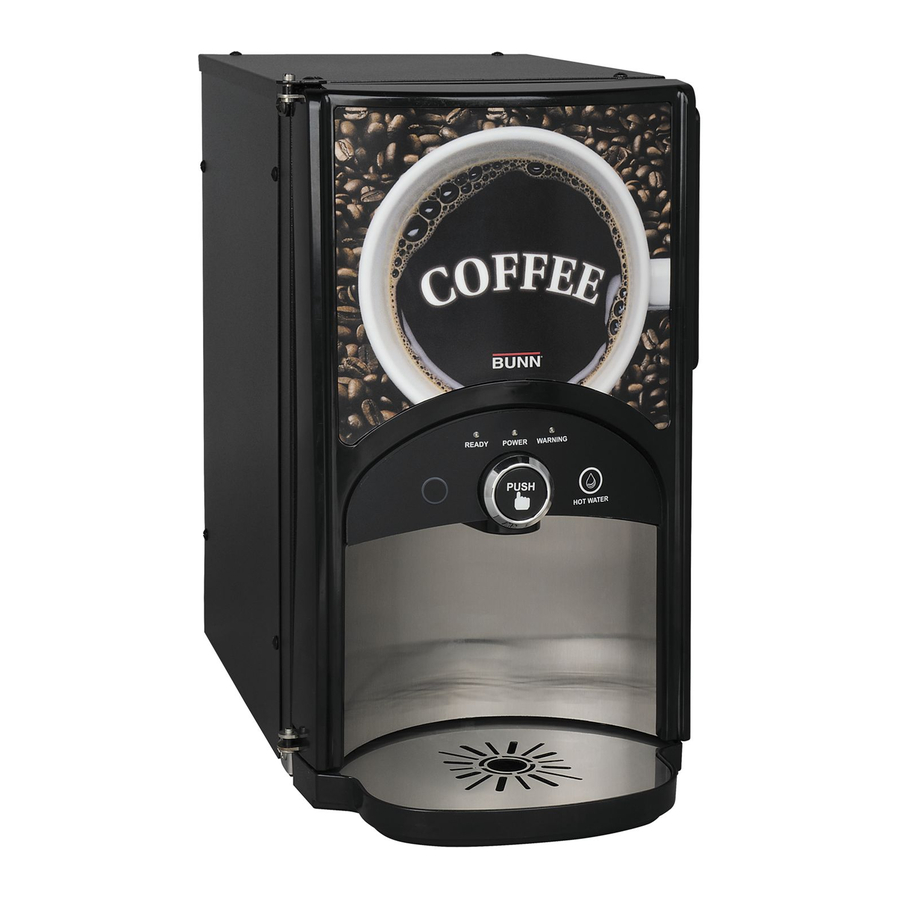
Page 5: Introduction
INTRODUCTION The BUNN LCA-1 dispenser is design to hold up to 1/2 gal (2 l) of ambient - shelf stable liquid coffee concen- trate. The BUNN LCR-1 also holds up to 1/2 gal (2 l) of refrigerated liquid coffee concentrate. Both dispensers are designed to operate when ambient temperatures are from 32°F (0°C) minimum to 95°F (35°C) maximum. -
Page 6: Initial Set-Up
INITIAL SET-UP NOTE: The LCA-1 weighs approximately 40 lbs. (18 kg) and the LCR-1 weighs approximately 55 lbs. (25 kg), when empty. If necessary, use more than one person when lifting or moving the dispenser. 1. Cut the plastic bands and remove the top box and other packing. 2. -
Page 7: Operating Controls & Interface
OPERATING CONTROLS AND INTERFACE User Interface: 1. Dispense Switch: Push and Hold to dispense product. 2. Hot Water Switch: Push and Hold to dispense hot water only. 3. Portion Switch: Momentarily pushed to select a Portion dispense. 4. Power LED: Red - illuminates when AC power is applied to dispenser. 5. - Page 8 OPERATING CONTROLS AND INTERFACE (Continued) Selector Switches: (Located behind the splash guard panel) Left Sw: a. Prime: Dispenses concentrates only – Primes the concentrate pump. b. Normal: Normal dispense mode - Dispenses mixed product (concentrate and water). c. Rinse: Dispenses hot water only- Flushes the dispense tip. Right Sw: a.
-
Page 9: Installing Pump Tubing
5. Inspect pump bands for signs of wear and replace if necessary. 6. Apply lubricant (BUNN-O-MATIC part no. M2548.1000) to the middle section of the new pump tubing.(Fig 2) 7. Wrap the new pump tubing around the rotor, making sure the elbow is snug against the inlet of the pump.(Fig3) 8. -
Page 10: Initial Fill & Heat
INITIAL FILL & HEAT 1. Select Normal and Run on the Selector switches. 2. Confirm the water supply is on. 3. Connect the dispenser to the power source. 4. The Red POWER LED will illuminate and water will begin flowing into the tank. The dispenser will automatically stop filling when the tank is full. -
Page 11: Rinse Alarm Feature
Rinse Alarm Feature Periodic rinsing of the dispense tip is essential for proper maintenance and optimum performance of the dispenser. The automated Rinse Alarm feature has two levels of operation, Disabled and Warning. Level Selected Alarm Disabled None Warning Warning LED will come on 4 hrs prior to the selected time interval and remain on until the Rinse procedure has been performed. -
Page 12: Programming The Dispenser
PROGRAMMING THE DISPENSER Two basic modes are available to the operator: Display Mode and Program Mode. Open the dispenser door to access the digital Programming Switches with LED display. To enter the Display Mode, Set the RUN/NIGHT/ PROGRAM Switch to the RUN position. Display Mode: Used to view the current set-up values. - Page 13 PROGRAMMING THE DISPENSER (Cont.) Program Mode : Used to change or enter new set-up values. To enter the Program Mode, Set the RUN/NIGHT/PROGRAM Switch to the PROGRAM position, the unit will display “__PPP” to indicate it is in the Program Mode. Use the MENU switch to scroll to the next display. Use the Increase (+) and Decrease (-) switch to adjust the values.
-
Page 14: Operating The Dispenser
OPERATING THE DISPENSER Set the Function Selector Switch to “Normal” and the Mode Selector Switch to “Run.” 1A. Push and Hold Dispense Mode (Cup at a time). a. Place cup on the tray beneath the dispensing tip. b. Push and hold the Dispense Switch until the cup is nearly full. c. -
Page 15: Cleaning & Preventive Maintenance
GENERAL CLEANING AND SANITIZING PROCEDURES Note: The BUNN® LCA-1 & LCR-1 dispensers incorporates a “user selectable” rinse reminder feature, which displays warning LED on the front panel when it is time to rinse. See Programming Functions to activate this feature. -
Page 16: Replacing The Pump Tubing
How long the tubes last is dependent on usage and properties of the concentrate. Excessive wear will reduce the output of the pumps resulting in a weak mixed beverage. Bunn-O-Matic recommends replacing the Pump Tubing a minimum of once every 6 months or sooner if warranted. -
Page 17: Calibrating The Dispenser
CALIBRATING THE DISPENSER NOTE: The LCA/LCR-1 is calibrated at the factory and does not normally need to be re-calibrated. Open the dispenser door to access the digital Programming Switches with LED display. To enter the Calibration Mode, Set the RUN/NIGHT/PROGRAM Switch to the PROGRAM position and then hold both Up and Down Arrow switches until “1 r u n”... - Page 18 CALIBRATING THE DISPENSER (Cont.) LED DISPLAY CALIBRATION MODE DESCRIPTION 6 - - - Reset Factory Defaults Resets all set up values to the Factory Default setting. Reset by holding the Decrease (-) switches for 10 sec. Currently have to hold (+) & (-) MENU _ 2 0 0 Pump “OFF”...
-
Page 19: Troubleshooting Guide
Error # shown on the display. Refer to the list of Error Codes below to identify the problem. The troubleshooting guide is provided to suggest probable causes and remedies for most problems. If the problem remains after exhausting the troubleshooting steps, contact the Bunn-O-Matic Technical Service Department. LED DISPLAY... - Page 20 TROUBLESHOOTING GUIDE (Cont.) Error Codes (Continued) The Follow errors codes apply to the LCR-1 only. LED DISPLAY ERROR DESCRIPTION/TROUBLESHOOTING E _ 0 Sensor reading Out Of Range (High or Cool Temp Sensor Failed Low). Check Sensor wires for shorts or open connections.
-
Page 21: Calibration Of The Concentrate Pumps
CALIBRATION OF THE CONCENTRATE PUMP & DISPENSER FLOW RATE The factory set default values for the Pump & Dispenser Flow Rates are very accurate and typically do not need to be field calibrated. However, if the mix ratio accuracy is ever in question, this procedure can be used to reca- librate the unit in the field. -
Page 22: Draining The Hot Water
CALIBRATION OF THE CONCENTRATE PUMP & DISPENSER FLOW RATE (Continued) Calibrating the Dispenser Flow Rates. 1. Select RINSE on the Selector Switch. 2. Press the Down Arrow switch to display the Flow Rate calibration menu “2 run” 3. Place a container under dispense tip and depress the dispense switch until a steady stream of water comes out the tip (5 to 10 seconds). -
Page 23: Schematic Wiring Diagrams
MEMBRANE SWITCH CONDENSER FAN J11-1 PROGRAM CONDENSER J2-1 J11-5 WHI/ORG J2-4 RELAY TRANSFORMER COIL PRIMARY WHI/ORG CONTACT WHT/GRN SECONDARY CONTACT BLU/BLK 120 VOLTS AC 2 WIRE + GRD SINGLE PHASE, 60 HZ 44869.0000B 08/11 © 2011 Bunn-O-Matic Corporation 44806.1 081211...
Need help?
Do you have a question about the LCA-1 and is the answer not in the manual?
Questions and answers