Bunn LPG Operating & Service Manual
Hide thumbs
Also See for LPG:
- Installation and operating manual (6 pages) ,
- Installation & operating manual (6 pages) ,
- Specification (2 pages)
Table of Contents
Advertisement
BUNN
OPERATING & SERVICE MANUAL
27091.0000 8/01 ©1996 Bunn-O-Matic Corporation
BUNN-O-MATIC CORPORATION
POST OFFICE BOX 3227
SPRINGFIELD, ILLINOIS 62708-3227
PHONE: (217) 529-6601 FAX: (217) 529-6644
®
LPG-2E
LPG
S T
F /
O F
s .
r a il
t o
l in
n .
n e
it io
u n
o s
e f
T
" p
s li d
A R
R T
S T
n d
T A
d .
l a
" S
h e
n e
t o
f u n
in is
it c h
n f
t o
s w
r in
h e
t h e
p w
f il t e
s t o
s h
c e
p u
ll y
P la
r il y
t ic a
1 .
n t a
m a
m e
u t o
M o
l a
w il
2 .
e r
in d
G r
3 .
www.bunnomatic.com
O P
Advertisement
Table of Contents

Subscribe to Our Youtube Channel
Related Manuals for Bunn LPG


Summary of Contents for Bunn LPG
- Page 1 OPERATING & SERVICE MANUAL BUNN-O-MATIC CORPORATION POST OFFICE BOX 3227 SPRINGFIELD, ILLINOIS 62708-3227 PHONE: (217) 529-6601 FAX: (217) 529-6644 www.bunnomatic.com 27091.0000 8/01 ©1996 Bunn-O-Matic Corporation...
-
Page 2: Table Of Contents
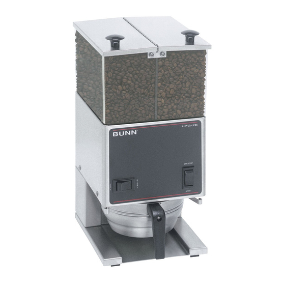
INTRODUCTION The LPG will store up to six pounds and the LPG-2E will store up to three pounds of whole bean coffee in each of two hoppers and grind it to a preset grind and amount into an awaiting funnel and filter from most commercial drip coffee brewers. -
Page 3: User Notices
60 Hz for 120V models; 100 volts ac, 15 amp single phase, 50Hz for 100V models; and 230 volts ac, 10 amp single phase, 50 Hz for 230V models. OPERATING CONTROLS Off/On/Start Switch (Models LPG and LPG-2E) OFF - (upper position) Switching to this position stops all operation of the grinder. -
Page 4: Cleaning
9. Refer to Initial Set-up/Adjustments section to vary grind or weight of dispensed coffee if necessary. COFFEE GRINDING 1. On models LPG-2E, select (either left or right hopper) with selector switch and visually inspect the desired hopper for an ample supply of whole bean coffee. -
Page 5: Initial Set-Up
REGULAR (COARSE) GRIND: Rotate the adjusting screw 10 hash marks in a counterclockwise direction. NOTE: Exact adjustment will vary according to bean roast or added flavoring. Timer Adjustment (Model LPG-2E) 1. Fill hoppers with whole bean coffee and select hopper to be adjusted. -
Page 6: Troubleshooting
TROUBLESHOOTING A troubleshooting guide is provided to suggest probable causes and remedies for the most likely problems encountered. If the problem remains after exhausting the troubleshooting steps, contact the Bunn-O-Matic Technical Service Department. • Inspection, testing, and repair of electrical equipment should be performed only by qualified service personnel. - Page 7 Foreign materials must not block the openings at the bottom of the hopper(s). Refer to Service - Solenoids for test- 3. Slide Gate Solenoids (Model LPG-2E only) ing procedures. See page 14 4. Timer Refer to Service - Timer for testing procedures. See page 16 Incorrect amount of coffee.
-
Page 8: Service
Remove the four #8-32 screws securing the rear panel and knob cover for Model LPG-2E, to the hop- per housing. On Model LPG-2E, let the rear panel hang by the orange and brown wires from the timer board. -
Page 9: Capacitor
The circuit breaker is located on the rear of the BLK from Power Cord grinder next to the power cord strain relief bushing. The circuit breaker is not available on Model LPG P1037 equipped with capacitor. FIG. 6 CIRCUIT BREAKER TERMINALS... -
Page 10: Dechaffer
SERVICE (cont.) Hopper Selector Switch (Model LPG-2E) Dechaffer P1029 FIG. 9 HOPPER SELECTOR SWITCH Location: The Hopper Selector Switch is located in the lower left front of the hopper housing. P1062 FIG. 7 DECHAFFER Test Procedure: Location: 1. Disconnect grinder from the power supply. -
Page 11: Motor
If continuity is present the overload is good. NOTE: Steps 5 thru 14 apply only to Model LPG-2E. If continuity is not present the overload will not reset, replace the motor. 5. Refer to Fig.13. Remove the three #8-32 Keps nuts. - Page 12 SERVICE (cont.) Motor (cont.) 9. Slide spacer plate (4) off of burr housing divider (8) and set aside for reassembly. 10. Loosen the #10-32 setscrew (5) securing the mounting ring and solenoid bracket (6) to the burr housing. 11. Lift mounting ring, solenoid bracket and solenoids (6) over the motor and burr housing assembly (9) and set aside for reassembly.
- Page 13 38. Reconnect wires for motor and solenoids. Refer to sembly (17) using two #10-32 fillister head screws. wiring schematic on page 18. 31. Set motor upright with burr housing at the bottom. NOTE: Steps 32 thru 36 apply only to Model LPG-2E. 27091 111598...
-
Page 14: Off/On/Start Switch
4. Reconnect all the wires to the switch terminals. 5. Refer to Fig. 16 when reconnecting the wires. YEL to Timer P1-5 - LPG-2E RED from Motor WHI/BRN to Timer P1-5 - LPG... - Page 15 SERVICE (cont.) Solenoid (cont.) solenoid with a voltmeter. Connect the grinder to the power source and place the Off/On/Start switch in the “ON” center position. The indication must be 120 volts AC. 4. Disconnect the grinder from the power source. If voltage is present as described, proceed to #5.
-
Page 16: Timer
SERVICE (cont.) 7. Place the hopper selector switch in the right posi- Timer (Model LPG-2E) tion. 8. Insert the leads of a voltmeter set to read at least 120 volts AC, along side the red wire (terminal 8) and the violet wire (terminal 9) of the harness plug. - Page 17 SERVICE (cont.) Timer (Model LPG-2E) 3. Disconnect the grinder from the power source. 8. Slip timer and timer mounting bracket under the two screws on the motor support plate and tighten screws. If voltage is present as described, proceed to step #4.
-
Page 18: Wiring Schematics
LPG2E SELECTOR SWITCH TIMER ASSY. GRINDER (Hopper Slide Gate Timer WHI/BLK Dial Wiring) Right - Brown Left - Orange OFF/ON/START SLIDE GATES SWITCH 120 VOLTS AC 27103.0000C 11/98 © 1996 2 WIRE BUNN-O-MATIC CORPORATION SINGLE PHASE 60 HZ 27091 111598... - Page 19 SCHEMATIC WIRING DIAGRAM LPG & LPG2 GREEN WHI/BLK WHI/BLK WHI/BLU WHI/BLU TIMER WHI/BRN WHI/BRN WHI/BRN WHI/BRN WHI/BLU WHI/BLU MOTOR 10529.0000C 3/92 © 1990 120 VOLTS AC BUNN-O-MATIC CORPORATION 2 WIRE SINGLE PHASE 60 HZ 27091 111598...
- Page 20 WIRING SCHEMATICS SCHEMATIC WIRING DIAGRAM LPG-A GRN/YEL WHI/BLK WHI/BLK WHI/BLU WHI/BLU TIMER WHI/BRN WHI/BRN WHI/BRN WHI/BRN WHI/BLU WHI/BLU MOTOR 10529.0002E 8/01 © 1990 230 VOLTS AC BUNN-O-MATIC CORPORATION 2 WIRE SINGLE PHASE 50/60 HZ 27091 082701...
- Page 21 SCHEMATIC WIRING DIAGRAM LPG W/Capacitor GREEN WHI/BLK WHI/BLK WHI/BLU WHI/BLU TIMER WHI/BRN WHI/BRN WHI/BRN WHI/BRN WHI/BRN WHI/BRN WHI/BLU WHI/BLU MOTOR 10529.0003E 10/98 © 1998 120 VOLTS AC 2 WIRE BUNN-O-MATIC CORPORATION SINGLE PHASE 60 HZ 27091 111598...
- Page 22 WIRING SCHEMATICS SCHEMATIC WIRING DIAGRAM LPG-B GREEN WHI/BLK WHI/BLK WHI/BLU WHI/BLU TIMER WHI/BRN WHI/BRN WHI/BRN WHI/BRN WHI/BLU WHI/BLU MOTOR 10529.0001D 10/98 © 1990 100 VOLTS AC BUNN-O-MATIC CORPORATION 2 WIRE SINGLE PHASE 50-60 HZ 27091 111598...
Need help?
Do you have a question about the LPG and is the answer not in the manual?
Questions and answers