Table of Contents
Advertisement
Advertisement
Table of Contents

Related Manuals for Phonic POWERPOD K-16 PLUS


Summary of Contents for Phonic POWERPOD K-16 PLUS
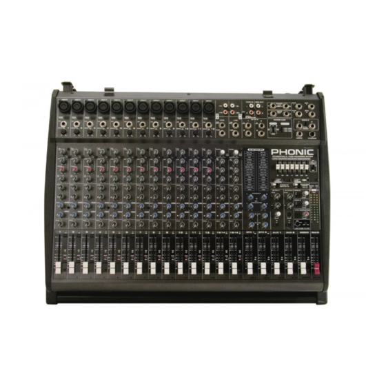
- Page 1 POWERPOD K16 PLUS POWERED MIXER...
-
Page 2: Important Safety Instructions
IMPORTANT SAFETY INSTRUCTIONS The apparatus shall not be exposed to dripping or splashing and that no objects with liquids, such as vases, shall be placed on the apparatus. The MAINS plug is used as the disconnect device, the disconnect device shall remain readily operable. -
Page 3: Table Of Contents
APPENDIXB: Dimensions................20 APPENDIX C: Typical Connecting Leads.............. .21 APPENDIX D: Block Diagram................2 2 Phonic preserves the right to improve or alter any information within this document without prior notice. V1.0 DEC 8,2006... -
Page 4: Introduction
• Dual DFX, our 32/40-bit digital multi-effect pro- all of Phonic’s products and is sure to be a valu- cessor with 100 programs plus tap control, Test able investment. To ensure, however, that you... -
Page 5: Basic Setup
BASIC SETUP Getting Started Channel Setup 1. Ensure all power is turned off on the Power- 1. To ensure the correct audio levels of each pod K-16 Plus. To totally ensure this, the AC input channel is selected, every channel cable should not be connected to the unit. -
Page 6: The Protective Molded Cover
The Protective Molded Cover Opening the cover pull up to open. Removing the cover Place the small connecting rods of the Attaching the cover molded cover underneath mixer's hooks. POWERPOD K16 Plus PLUS... -
Page 7: Making Connections
MAKING CONNECTIONS Master Section Channel Inputs 4. Tape Inputs These inputs accom- 1. Combo Jack Inputs modate RCA connec- These inputs are for bal- tions from such devices anced and unbalanced as tape and CD players. signals, accepting both The line from this feed is XLR and 1/4”... -
Page 8: Rear Panel
Rear Panel 10. AUX 1 and 2 Outputs These phone jack outputs are the final output 15. Speaker Outputs of line-level signal fed from the corresponding Use this jacks to connect your speakers, fed auxiliary mixing bus, and are best suited for use from the internal power amp. -
Page 9: Controls And Settings
CONTROLS AND SETTINGS Channel Controls Powering the Unit 19. PAD Control The PAD control located at channels 1 to 8 is 17. Power Button and AC Connector used to attenuate the channel input signal by 26 The power button, located on the rear of the Box dB. - Page 10 23. MF (Parametric Middle Frequency) Control 28. On Button and Indicator This control is used to provide a peaking style This turns the channel on, allowing the user to of boost and cut to the level of middle frequency use the feed from the channel’s inputs to supply (100 Hz - 8 kHz) sounds at a range of ±15 dB.
-
Page 11: Digital Effects Panel
33. Stereo Channel A/B Button 36. Program Control When this button is released, the K-16 Plus’s This control is used to scroll through the various stereo channels (13/14, 15/16) will receive their effect numbers shown on the Digital Effect Dis- signals from the 1/4”... -
Page 12: Master Section
AUX 1 / L/R button to the same setting as the FBD button to ensure simpler adjustment of frequencies that have produced feedback. 42. Solid Phonic System Using this switch will enable the user to give both the high and low frequencies of their sound a little boost to improve the overall robustness of the audio. - Page 13 45. Stand-by Switch and Indicator 49. Control Room / Phones Control This switch enables and disables a mute of chan- This knob controls the level of the audio to be nels 1 through 12 on the K-16 Plus. This feature sent to the Control Room and Phones outputs, is handy in live performances, due to the fact that located on the top panel of the K-16 Plus mix-...
- Page 14 52. Mono Channel Controls 55. PFL/AFL Indicator The Mono Channel fader will adjust the final au- The PFL/AFL indicator on the top of this meter dio level that is to be sent to the Mono output is bi-colored, and illuminates green when a PFL jack.
-
Page 15: Applications
APPLICATIONS There are potentially hundreds of ways to connect instruments and devices to the Powerpod K-16 Plus Powered Mixers. It is advisable that you explore the functions and find the best setup possible for your needs, which may depend on what instruments you wish to connect, as well as how many external devices you wish to connect and your required monitoring applications. -
Page 16: Adding External Parallel Devices
Adding External Parallel Devices POWERPOD K16 Plus PLUS... -
Page 17: Specifications
SPECIFICATIONS POWERPOD K16 PLUS POWER AMP, output power in Watts @THD<0.5%, 1KHz Number of Power Channels Limiters 8 ohms per Channel 4 ohms per Channel 8 ohms Bridge Mono 1000 Power Amp Select Switch 500W+500W, 300W+300W, 100W+100W Inputs Total Channels Balanced Mono Mic/Line Channels 12 (XLR + 1/4”... - Page 18 Power output, 1KHz, 20Hz to 20KHz Max@500 Watts, 4 ohms <0.5% Any output, 1KHz @ +14dBu, 20Hz to 20KHz, channel inputs <0.3% CMRR 1 KHz @ -60dBu, Gain at maximum 80 dB Crosstalk 1KHz @ 0dBu, 20Hz to 20KHz bandwidth, channel in to main L/R outputs Channel fader down, other channels at unity <-63 dB...
-
Page 19: Appendix A: Digital Effect Table
APPENDIX A: Digital Effect Table PROGRAM NAME PARAMETER SETTING PROGRAM NAME PARAMETER SETTING ROOM REV-TIME EARLY LEVEL SPEED TYPE COMPACT ROOM 1 0.05 SLOW PAN R-->L COMPACT ROOM 2 SLOW PAN 1 R<-->L SMALL ROOM 1 0.45 SLOW PAN 2 R-->L SMALL ROOM 2 MID SHIFT... -
Page 20: Appendixb: Dimensions
APPENDIX B: Dimensions * All measurements are shown in mm/inches. POWERPOD K16 Plus PLUS... -
Page 21: Appendix C: Typical Connecting Leads
APPENDIX C: Typical Connecting Leads POWERPOD K16 PLUS... -
Page 22: Appendix D: Block Diagram
APPENDIX D: Block Diagram POWERPOD K16 Plus PLUS... - Page 23 Phonic, at its option, shall repair or replace the defective unit covered by this warranty. Please retain the dated sales receipt as evidence of the date of purchase.
Need help?
Do you have a question about the POWERPOD K-16 PLUS and is the answer not in the manual?
Questions and answers