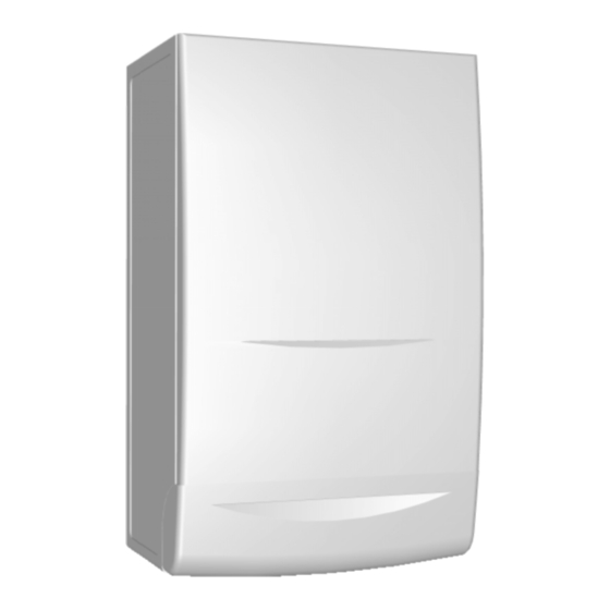
Ferroli Domina 102 Installation, Servicing And User Instructions Manual
Coper wall-mounted combination, gas fired boiler for central heating and domestic hot water production, fan assisted, room sealed compartment, electronic flame ignition and control
Hide thumbs
Also See for Domina 102:
Summary of Contents for Ferroli Domina 102
- Page 1 OPPER OUNTED OMBIN TION IRED OILER FOR ENTR L E TING OMESTIC RODUCTION SSISTED E LED OMP RTMENT LECTRONIC L ME GNITION ONTROL...
- Page 4 Bottom view Top view Ø80 Ø80 Ø80...
- Page 5 Domestic hot Domestic hot Heat input water heat Boiler water Heat output water circuit input contents MODEL contents Gross Litres Litres Domina 102 30,0 12,7 33,1 14,5 30,0 Max. working Max. Connections Expansion vessel pressure working central pressure hot MODEL heating water circuit Pre-pressurising...
- Page 6 FLUE FERROLI GRUNDFOS 85 44 C.H. D.H.W. D.H.W. C.H.
- Page 7 12 13 14 15 16 17 18 19 20 21 22 23 24 25 26 27 28 29 30 31 12 13 14 15 16 17 18 19 20 21 22 23 25 26 27 28 29 30 kcal/h kcal/h 11 12 13 14 15 16 17 18 19 20...
- Page 8 mbar x 100 m |h...
- Page 11 5 min. 5 min. 50 mm 600* min. D, E Balanced flues room Open flues sealed Dimensions Terminal position (kW input expressed in net) Natural Fanned Natural Fanned draught draught draught draught Directly below an opening, air brick, (0-7 kW) 300 mm 300 mm Not allowed...
- Page 12 Ø120 jig bracket Ø3/4'' Ø1/2'' Ø1/2'' Ø1/2'' Ø1/2'' Ø3/4'' 1 2 3 460 min 5 min...
- Page 13 Holes Ø : 47 50 52 RESTRICTOR FOR TWO PIPE SYSTEM ON DOMINA 102 Total flow resistance restrictor of flue system size minimum maximum 20 m 20 m 35 m 35 m 45 m 45 m 50 m no restrictor...
- Page 14 1KWMA31Y * = between 10 e 60 mm Ø60 Ø80 -3 mm/m 70 min.
- Page 15 100 mm concentric 125 mm concentric Maximum flue lenght permissible Vertical Horizontal* Vertical Horizontal* Domina 102 Reduction for bend 100 mm concentric bend 90 100 mm concentric bend 45 0,5 m 125 mm concentric bend 90 0,5 m 125 mm concentric bend 45 , 0,25 m max.
- Page 16 Ø80 Ø80 FLUE...
- Page 17 REDUCTION REDUCTION FLUE FLUE Description Dscription Male-female flue/Air pipe Horizontal 1 m - Ø 80 flue terminal Ø 80 mm Female-female bend Air intake 45 Ø 80 m terminal Ø 80 mm Male-female bend Outlet flue/air inlet 90 Ø 80 m for concentric system Ø...
- Page 18 13 m 13 m...
- Page 21 JP03 Nat/LPG JP02 JP01 CLOCK MF03F JP03 1 2 3 5 Nat/LPG JP02 JP01 CLOCK MF03F...
- Page 35 Chek the following carefully before starting • Gas supply is turned on, is adequate and purged • Electricity supply is turned on • Polarity is correct • CH pressure is set between 1 - 1,5 bar • CH pump spins freely D.H.W.
- Page 36 Open DHW taps DHW flow rate at least 2,5 litre/min? Check cold water inlet pressure Check and if necessary Is LED3 on? replace DHW Sensor Check if water filter is clean Check and if necessary replace Flow Sensor Is LED4 flashing? Check and if necessary replace main board Is relay RY100 switch on?
- Page 37 Does fan run? Is air pressure switch activated? Is relay RY100 switch ON? Go to chart 5 Differential air pressure across the air pressure Go to charts 2-3 switch is greater than 180 Pascal? Check and if necessary replace Is 230V present across air pressure switch fan terminals? Check and clean fan...
- Page 38 Is LED1 light on? Is LED2 on Does sparking start without at burner? the boiler sparking Does burner light? Go to chart 5 Re-check air pressure switch Check and if necessary Is LED2 on replace safety thermostat after 10 seconds? Check electrodes and Check and if necessary leads for damage...
- Page 39 MV1 MV2 MV3 MV4 JP03 RY101 RY100 Nat/LPG JP02 Transformer JP01 MF03F...
- Page 40 Blue Blue Blue Blue Blue Blue Blue Blue Blue...
- Page 41 KEY DESCRIPTION Switch OFF/ON/RESET Burner on indicator Central heating flow temperature regulation Boiler shut down warning D.H.W. temperature Domestic hot water circuit on regulation Central heating stand-by (Flashing light) Water pressure gauge Central heating circuit on (Permanent light) Insufficient pressure in central heating system (Flashing light) Time clock (option) Electric power supply (Permanent light)
- Page 43 AUTO AUTO OVER RIDE 6:00 6:30 8:30 9:00 12:00 12:30 12:00 14:00 16:30 16:00 22:30 23:30...


Need help?
Do you have a question about the Domina 102 and is the answer not in the manual?
Questions and answers