Advertisement
RENDIMAX CE
RENDIMAX CE
RENDIMAX CE
RENDIMAX CE
RENDIMAX CE
CAST IRON GAS-FIRED BOILER
CAST IRON GAS-FIRED BOILER
CAST IRON GAS-FIRED BOILER
CAST IRON GAS-FIRED BOILER
CAST IRON GAS-FIRED BOILER
for central heating
for central heating
for central heating
for central heating
for central heating
Installation and operating instructions
Installation and operating instructions
Installation and operating instructions
Installation and operating instructions
Installation and operating instructions
S.p.A.
Advertisement

Subscribe to Our Youtube Channel
Related Manuals for Ferroli Rendimax 23 CE


Summary of Contents for Ferroli Rendimax 23 CE
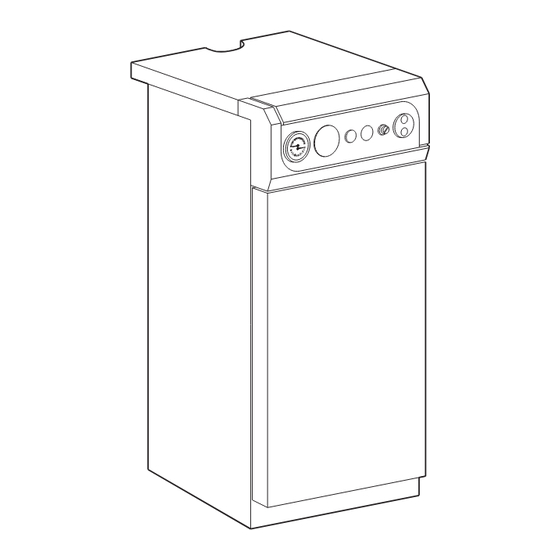
- Page 1 S.p.A. RENDIMAX CE RENDIMAX CE RENDIMAX CE RENDIMAX CE RENDIMAX CE CAST IRON GAS-FIRED BOILER CAST IRON GAS-FIRED BOILER CAST IRON GAS-FIRED BOILER CAST IRON GAS-FIRED BOILER CAST IRON GAS-FIRED BOILER for central heating for central heating for central heating for central heating for central heating Installation and operating instructions...
-
Page 2: Table Of Contents
S.p.A. Contents Description Dimensions and technical specifications Installation Adjustment Gas conversion Maintenance and cleaning Troubleshooting... -
Page 3: Description
S.p.A. 1. DESCRIPTION 1.01 Introduction RENDIMAX CE boilers are heat generators for central heating and domestic hot water production. The standard version is designed to work with natural gas. To use the boiler with L.P.G., on-site conversion must be carried out following the instructions given below. - Page 4 S.p.A. 2.02 Components description View with open door Fig. 2 Boiler thermostat Boiler temperature / pressure gauge Safety valve Gas valve Circulation pump (only PV version) Boiler drain cock Pilot burner Piezo-Igniter Gas-Manifold Boiler main switch Filling cock Cock Flue thermostat...
-
Page 5: Installation
Rendimax 16 CE 16,2 14.000 11,0 9.500 18,0 15.500 12,7 11.000 23,0 19.800 16,0 13.800 25,5 22.000 18,4 15.800 Rendimax 23 CE Rendimax 30 CE 29,5 25.400 20,0 17.200 32,8 28.200 23,0 19.800 Rendimax 36 CE 36,0 31.000 24,0 20.600 40,0 34.400 27,6 23.800... - Page 6 S.p.A. Connection between boiler and chimney has to be sealed. The rated flow rate of gas counter has to be sufficient for the whole connected appliance. Be careful that the boilers connections are free of mechanical tensions. Connect the gas using a rigid pipe and including a gas cock. The boiler must be connected to a 230 Volt - 50 Hz single phase line (phase/neutral) by means of terminal board of approved socket.
- Page 7 S.p.A. 3.02 Checking and controlling the evacuation of combustion products (total security) The boiler is fitted with a FLUE GAS THERMOSTAT . This thermostat prevents gas from reaching the burner if the flue is not drawing properly, providing greater security and control over the discharge of combustion products.
- Page 8 S.p.A. 3.05 C.H. pump head characteristics (only P.V. version)(Fig. 5b) Fig. 5b NB - The diagram refers to maximum pump (Pos. 3) head/flow rate. 4. IGNITION AND SHUT-DOWN 4.01 Checks to carry out before igniting for the first time When igniting the boiler for the first time, it is good practice to check: - that the gate valves between the boiler and system are open;...
-
Page 9: Adjustment
S.p.A. Keep gas valve button 2 pushed down for 20 seconds then let it up slowly checking that the pilot burner remains lit. If it goes out, wait 30 seconds then repeat the ignition operation. Set the button 3 as shown in the fig. 3 Turn on the electricity to the boiler. - Page 10 S.p.A. 4.04 Igniting the boiler with SIT NOVA gas valve(fig 7b) Position the boiler thermostat 1 (fig. 2) on minimum. Open the gas cock and vent the air present in the tube upstream from the gas valve by opening the pressure point screw pos4.
-
Page 11: Gas Conversion
S.p.A. 4.05 Temporary shut-down To temporarily shut down the boiler, just position the main switch 6 on the “0” position.All the electrical part remain not energized and only the pilot burner remain alight. 4.06 Prolonged shut-down Push the button 4 (fig 6), turn clockwise the knob 1 (fig 7a) or turn the knob 1 in the position “C” (Fig. 7b). - Page 12 S.p.A. 5.02 Check and gas pressure regulation Gas Valve ELETTROSIT The regulation of gas pressure at the pilot burner has to be done at sight, without instrument but checking the that flame envelope completely the thermocouple (fig. 10) without burning excessive gas.
- Page 13 S.p.A. 5.05 Check and gas pressure regulation Gas Valve “HONEYWELL V4600C” The regulation of gas pressure at the pilot burner has to be done at sight , without instrument but checking the flame envelope completely the thermocouple (fig. 10) without burning excessive gas. To adjust the pilot flame operate on the screw 2 (fig.
- Page 14 S.p.A. 5.08 Heat output variability characteristics To adjust furnace heat input, simply regulate the main burner via the gas valve (fig. 8). This in turn varies the heat output to the C.H. water. The diagrams in Fig. 9a and 9b show the variations in heat output to the water in relation to variations in burner working pressure.
-
Page 15: Maintenance And Cleaning
S.p.A. 6. MAINTENANCE AND CLEANING The following operations must be carried out by qualified personnel only. The boiler requires no particular maintenance other than general control of boiler and chimney once a year.Each three years the at the end of heating season boiler burner and chimney has to be cleaned. 6.01 Seasonal control of boiler and flue Once a year before the heating season, the following controls should be carried out: - the burner and boiler body and chimney should be clean. - Page 16 S.p.A. 6.03 Cleaning the boiler and burner To clean the boiler and burner , proceed as follows: a) turn off the gas and the electricity supply upstream of the boiler. b) take out the boiler cover and the draft diverter cover (fig.11). c) disconnect the electric power supply cable to the valve.
-
Page 17: Troubleshooting
S.p.A. 7.TROUBLE SHOOTING Pilot burner fails to ignite No gas Open the gas cock Air in the pipes vent as described in the section on ignition Pilot nozzle blocked Clean the nozzle with compressed air Insufficient gas flow Adjust flow using the screw on the valve Pilot goes out Faulty thermocouple Control or replace the thermocouple... - Page 18 S.p.A. Incorrect flame regulation Check flow rate at the gas meter and pressure at the main burner Boiler functions, but temperature fails to rise Incorrect flame adjustment Check gas consumption is normal Boiler dirty Check and clean the boiler body Boiler inadequate Check that the boiler is the right size for the C.H.
- Page 19 S.p.A.
- Page 20 37047 SAN BONIFACIO - VR - ITALY 37047 SAN BONIFACIO - VR - ITALY 37047 SAN BONIFACIO - VR - ITALY 37047 SAN BONIFACIO - VR - ITALY 37047 SAN BONIFACIO - VR - ITALY tel. 045/6139411 - tlx. 480172 tel.
Need help?
Do you have a question about the Rendimax 23 CE and is the answer not in the manual?
Questions and answers