Table of Contents
Advertisement
WARRANTY
This radio is covered by a two
year limited parts and labor
warranty.
•
"Limited" means that we will repair problems caused by factory defects or
normal use at no charge.
•
Before returning a radio to us for warranty service, please call our Service
Department for a Repair Authorization Number (RAN). This RAN must be
written below your return address on the outside of the shipping box. Boxes,
which arrive without a RAN, will be refused, and the shipping company will
return the unopened box to you. Be sure to have a pen and paper ready along
with the serial number of your radio before calling. We will give you the RAN
and our shipping address over the phone. The telephone number of the Service
Department is (760) 480-8800, and we suggest calling between 10:00 AM and
4:00 PM Pacific Time.
•
Please include a note with a detailed description of the symptoms. This is
important because it will help the technician who works on your radio to locate
your problem. Intermittent problems are easily overlooked, so be sure to give as
much detail as possible in your note. Also, please include your telephone number
in case our technicians have any additional questions.
•
Do not send your power cord or microphone unless we ask for these items during
our telephone conversation.
•
You are responsible for getting the radio safely to us. (We suggest using United
Parcel Service.) You must pay to ship the radio to us, and we will pay to ship the
radio back to you. Since we use UPS and they do not ship to Post Offices boxes,
please provide us with a street address for the return of your radio.
•
We will repair and return your radio as soon as we can. We appreciate your
choosing a Galaxy radio and we want you to be on the air as much as possible!
Be sure to visit our web site at
www.GalaxyRadios.com
Printed In Malaysia
AT3602014R
PD000822
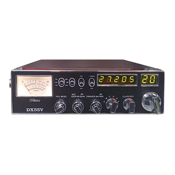
DX−55V
Full Channel AM/FM Mobile Transceiver
Built in Frequency Counter with Roger Beep
OWNER'S MANUAL
Advertisement
Table of Contents

Related Manuals for Galaxy DX-55V


Summary of Contents for Galaxy DX-55V
- Page 1 We will repair and return your radio as soon as we can. We appreciate your choosing a Galaxy radio and we want you to be on the air as much as possible! Be sure to visit our web site at www.GalaxyRadios.com...
-
Page 2: Table Of Contents
TABLE OF CONTENTS Specifications Page GENERAL Specification ........Channels 40 CH Frequency Range... -
Page 3: Location
RECEIVER Installation Sensitivity AM: 0.5 µV for 10 dB (S+N)/N at greater than ½ -watt of audio output. LOCATION FM: 1.0 µV for 20 dB (S+N)/N at greater Plan the location of the transceiver and microphone bracket before than ½-watt of audio output. starting the installation. -
Page 4: Ignition Noise Interference
IGNITION NOISE INTERFERENCE TUNNING THE ANTENNA FOR OPTIMUM SWR Use of a mobile receiver at low signal levels is normally limited by the Since there is such a wide variety of base and mobile antennas, this presence of electrical noise. The primary source of noise in automobile section will strictly concern itself to the various types of mobile adjustable installations is from the generator and ignition system in the vehicle. -
Page 5: External Speaker
C. Check your coaxial cable routing (it may be pinched when routed Operation into the car). D. Try a different location on your car (keeping in mind the radiation pattern you wish) CONTROL FUNCTIONS There are thirteen controls and three indicators on the front panel of E. - Page 6 14. +10KHz FREQUENCY SHIFT SWITCH. When switch is pressed the 5. DIMMER (inner dual concentric). Turns on/off the frequency display, frequency is shifted 10KHz up. On following channels. A channel can channel number and the meter lamp. Switch on at minimum brightness, be used by setting this switch to +10KHz position.
-
Page 7: Rear Panel
REAR PANEL PRESS-TO-TALK MICROPHONE The receiver and transmitter are controlled by the press-to-talk switch on the microphone. Press the switch and the transmitter is activated, release switch to receive. When transmitting, hold the microphone two inches from the mouth and speak clearly in a normal “voice”. The radios come complete with low-impedance (500 ohm) dynamic microphone. -
Page 8: Alternate Microphones And Installation
ALTERNATE MICROPHONES AND INSTALLATION For best results, the user should select a low-impedance dynamic type microphone or a transistorized microphone. Transistorized type microphones have a low output impedance characteristic. The microphones must be provided with a four-lead cable. The audio conductor and its shielded lead comprise two of the leads. - Page 9 MEMO Fig. 3 Microphone plug pin numbers viewed from rear of pin receptacle. Be sure that the housing and the knurled ring of Fig. 2 are pushed back onto the microphone cable before starting to solder. If the washer is not captive to the pin receptacle body, make sure that it is placed on the threaded portion of the pin receptacle body before soldering.
- Page 10 MEMO MEMO - 17 - - 18 -...
Need help?
Do you have a question about the DX-55V and is the answer not in the manual?
Questions and answers