Table of Contents
Advertisement
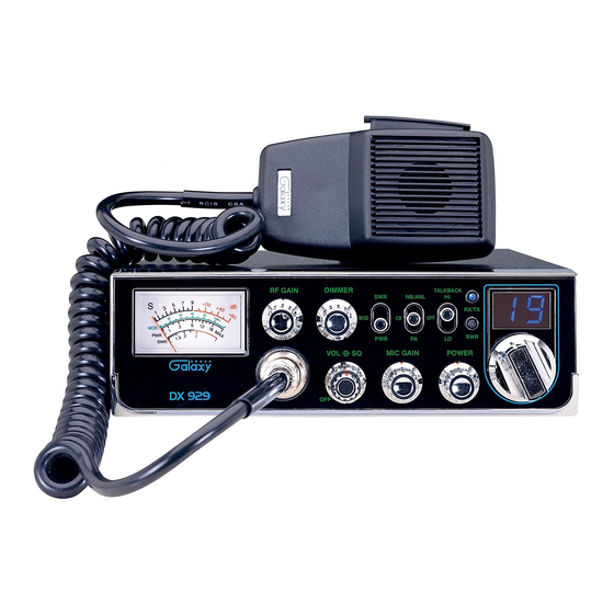
DX 929
Two Way
Citizens Band Mobile Transceiver
With StarLite Face Plate
OWNERS MANUAL
TABLE OF CONTENTS
CHAPTER 1
Specifications . . . . . . . . . . . . . . . . . . . . . . . . . . . . . . . . . . . . . . . . . . . . . . . .
CHAPTER 2
Installation . . . . . . . . . . . . . . . . . . . . . . . . . . . . . . . . . . . . . . . . . . . . . . . . . .
Installing The Radio . . . . . . . . . . . . . . . . . . . . . . . . . . . . . . . . . . . . . . . . . .
Ignition Noise Interference . . . . . . . . . . . . . . . . . . . . . . . . . . . . . . . . . . . . .
Antenna . . . . . . . . . . . . . . . . . . . . . . . . . . . . . . . . . . . . . . . . . . . . . . . . . . . .
External Speaker . . . . . . . . . . . . . . . . . . . . . . . . . . . . . . . . . . . . . . . . . . . . .
Public Address . . . . . . . . . . . . . . . . . . . . . . . . . . . . . . . . . . . . . . . . . . . . . .
CHAPTER 3
Operation . . . . . . . . . . . . . . . . . . . . . . . . . . . . . . . . . . . . . . . . . . . . . . . . . . .
Front Panel . . . . . . . . . . . . . . . . . . . . . . . . . . . . . . . . . . . . . . . . . . . . . . . . .
Rear Panel . . . . . . . . . . . . . . . . . . . . . . . . . . . . . . . . . . . . . . . . . . . . . . . . . .
Frequency Chart . . . . . . . . . . . . . . . . . . . . . . . . . . . . . . . . . . . . . . . . . . . . .
Procedure to Receive and Transmit . . . . . . . . . . . . . . . . . . . . . . . . . . . . . .
Alternate Microphone and Installation . . . . . . . . . . . . . . . . . . . . . . . . . . . .
Maintenance And Adjustment . . . . . . . . . . . . . . . . . . . . . . . . . . . . . . . . . .
A Few Rules That Should Be Obeyed . . . . . . . . . . . . . . . . . . . . . . . . . . . .
How Your CB Can Serve You . . . . . . . . . . . . . . . . . . . . . . . . . . . . . . . . . .
Use Channel 9 For Emergency Message Only . . . . . . . . . . . . . . . . . . . . . .
- 1 -
PAGE
2
3
3
4
4
4
4
5
5
8
9
10
11
14
15
15
16
Advertisement
Table of Contents

Subscribe to Our Youtube Channel
Related Manuals for Galaxy DX 929


Summary of Contents for Galaxy DX 929
-
Page 1: Table Of Contents
TABLE OF CONTENTS PAGE CHAPTER 1 Specifications ..........DX 929 CHAPTER 2 Installation . -
Page 2: Specifications
CHAPTER 1 SPECIFICATIONS CHAPTER 2 INSTALLATION GENERAL INSTALLING THE RADIO Choose a convenient location for operation that does not interfere with driver or Model DX 929 passenger. This radio is supplied with a universal mounting bracket. When mounting Channels the bracket and radio to your car, make sure it is mechanically strong. Also, provide a Frequency Range 26.965 ~ 27.405 MHz good electrical grounding connection to the chassis of vehicle. -
Page 3: Ignition Noise Interference
IGNITION NOISE INTERFERENCE CHAPTER 3 OPERATION With weak signals, you may experience interference of the signal by background noise. This radio has NB and ANL circuits which will help reduce background noise CONTROL FUNCTIONS from sources such as your ignition system. However, background electrical noise may FRONT PANEL come from several sources and all noise may not be eliminated. - Page 4 6. SWR LED: This LED lights red when your SWR is higher than about 3:1. This is 15. RX/TX LED: This LED is green during receive and red during transmit. not an exact indicator of 3:1 SWR, but it is an indication that you should check your SWR reading.
-
Page 5: Rear Panel
27.165 MHz 27.375 MHz 5. F.C.: This jack is used to connect the optional Galaxy FC347 six-digit frequency counter. All connections, including DC power, are provided to the FC347 through 27.175 MHz 27.385 MHz... -
Page 6: Procedure To Receive And Transmit
PROCEDURE TO RECEIVE AND TRANSMIT ALTERNATE MICROPHONES AND INSTALLATION A. MICROPHONE For best results, the user should select a low-impedance dynamic type microphone The push-to-talk switch on the microphone controls the receiver and transmitter. or a transistorized microphone. Transistorized type microphones have low output Press the switch and the transmitter is activated, release switch to receive. - Page 7 Before beginning the actual wiring, read carefully the circuit and wiring information 5. The wires must now be soldered to the pins as indicated in the above wiring tables. provided with the microphone you select. Use the minimum heat required in soldering If a vise or clamping tool is available it should be used to hold the pin receptacle the connections.
-
Page 8: Maintenance And Adjustment
A FEW RULES THAT SHOULD BE OBEYED 9. The two cable clamp retainer screws should now be tightened to secure the housing to the microphone cord. If the cutting directions have been carefully followed, the cable clamp should secure to the insulation jacket of the microphone 1. -
Page 9: Use Channel 9 For Emergency Message Only
USE CHANNEL 9 FOR EMERGENCY MESSAGES ONLY MEMO The FCC gives the following examples of permitted and prohibited types of communications for use in an emergency. These are guidelines and are not intended to be all inclusive. Permitted Example Message “A tornado sighted six miles north of town. - Page 10 MEMO MEMO...
- Page 11 We will repair and return your radio as soon as we can. We appreciate your choosing a Galaxy radio and we want you to be on the air as much as possible! You may download the complete Service Manual...
Need help?
Do you have a question about the DX 929 and is the answer not in the manual?
Questions and answers