
Related Manuals for Clarke G950


Summary of Contents for Clarke G950
- Page 1 900W PORTABLE GENERATOR MODEL NO: G950 PART NO: 8010105 OPERATION & MAINTENANCE INSTRUCTIONS LS0609...
-
Page 2: Introduction
INTRODUCTION Thank you for purchasing this CLARKE 900W Portable Generator Before attempting to use this product, please read this manual thoroughly and follow the instructions carefully. In doing so you will ensure the safety of yourself and that of others around you, and you can look forward to your purchase giving you long and satisfactory service. -
Page 3: Table Of Contents
TABLE OF CONTENTS INTRODUCTION ............... 2 GUARANTEE ..............2 PARTS AND SERVICING ..........2 TABLE OF CONTENTS ............3 GENERAL SAFETY RULES ..........4 Work area ..................4 Positioning the generator .............. 4 Fire prevention ................4 Prevention of electric shock ............5 Additional safety rules for generators .......... -
Page 4: General Safety Rules
GENERAL SAFETY RULES WARNING: EXHAUST FUMES CAN BE EXTREMELY DANGEROUS IF INHALED WORK AREA • Always use in a well ventilated area. • Always position the exhaust outlet away from people. • Read these safety instructions before using the equipment. •... -
Page 5: Prevention Of Electric Shock
6. Never start the engine if there is spilled fuel. Any spillage must be wiped clean and the generator allowed to dry before attempting to start the engine. PREVENTION OF ELECTRIC SHOCK 1. Never use the generator in wet conditions unless it is well protected/ covered. -
Page 6: Safety Symbols
SAFETY SYMBOLS Caution - The user should be aware of a general hazard Dangerous Voltage Flammable Hot Surface - Do not touch Poisonous fumes - Do not use the generator in an enclosed space. Read Instruction manual before use. -
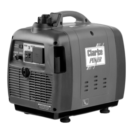
Page 7: Generator Overview
GENERATOR OVERVIEW DESCRIPTION NO DESCRIPTION Air Vent Knob Engine ON/OFF Switch Fuel Cap Earthing Point Fuel Valve Knob AC Socket Starting Handle DC Socket Right Side Maintenance Cover DC Circuit Breaker Left Side Maintenance Cover Overload Indicator Exhaust Engine Speed Adjustment (DO NOT ADJUST THIS) Choke Muffler... -
Page 8: Unpacking And Assembly
• 1 x Double Ended Screwdriver • 1 x Fabric Tool Pouch • 1 x 12 Volt Battery Charging Lead with Battery Clips Should there be any missing or damaged in transit contact your Clarke dealer immediately. BEFORE USING THE GENERATOR IMPORTANT: Generators should ALWAYS be earthed. -
Page 9: Checking The Engine Oil Level
WARNING: TO CARRY OUT THIS CHECK, SWITCH THE ENGINE OFF. WARNING: TAKE CARE NOT TO TOUCH ANY HOT PARTS OF THE GENERATOR WHEN CHECKING THE OIL LEVEL. CHECKING THE ENGINE OIL LEVEL NOTE: Place the generator on a level surface and check the oil level as follows. -
Page 10: Checking The Fuel Level
CHECKING THE FUEL LEVEL Make sure there is sufficient fuel in the tank. 1. To check the fuel level, open the fuel filler cap. 2. Slowly add fuel to the fuel tank (maximum 5L) • Do not overfill the fuel tank. 3. -
Page 11: Using Your Generator
USING YOUR GENERATOR STARTING THE ENGINE 1. Remove all connections from the AC sockets. 2. Hold the fuel tank cap so that it will not move, and turn the air vent knob counterclockwise to open the fuel tank air vent. 3. - Page 12 NOTE: When you first start the generator, the overload indicator may light up for a few seconds, this is normal. If the overload indicator is still lit after 5 seconds, stop the engine and contact your Clarke dealer. 7. Once the engine has warmed up,...
-
Page 13: Connecting Electrical Devices
CONNECTING ELECTRICAL DEVICES The generator can supply both 230V AC and 12V DC AC POWER 1. Start the engine. See page 11. 2. Make sure the appliance is turned off before connecting it to the generator. 3. Connect the appliance to the generator. - Page 14 DC POWER For charging car batteries only CAUTION: MAKE CONNECTIONS TO THE BATTERY AFTER STARTING THE ENGINE. 1. Start the generator, See page 11. 2. Connect the battery charging leads to the generator. 3. Connect the battery charging leads to the battery. •...
-
Page 15: Shutting Down The Generator
SHUTTING DOWN THE GENERATOR To stop the generator in an emergency simply set the engine switch to ‘OFF’. NOTE: Turn off any electric devices. NOTE: Set the economy control switch to the ‘0’ (OFF) position. 1. Disconnect any electric devices. 2. -
Page 16: Maintenance
MAINTENANCE CHANGING THE ENGINE OIL CAUTION: PROLONGED EXPOSURE TO USED ENGINE OIL IS DANGEROUS, ALWAYS WASH YOUR HANDS THOROUGHLY AFTER HANDLING USED ENGINE OIL. 1. Remove the left side maintenance panel. 2. Turn the oil filler cap anti- clockwise and remove from the oil tank, wipe the dipstick with a clean cloth. -
Page 17: Changing The Spark Plugs
CHANGING THE SPARK PLUGS CAUTION: ALLOW THE ENGINE TO COOL BEFORE REMOVING THE SPARK PLUG. 1. Remove the spark plug maintenance panel. 2. Remove the spark plug cap from the spark plug. 3. Use a spark plug spanner (supplied) to remove the spark plug. -
Page 18: Troubleshooting
900W. (dc supply only) The DC Press the reset button. See page 14 Overload protector has activated. If this does not solve your problem, please contact the Clarke service department. See page 2... -
Page 19: Specifications
SPECIFICATIONS G950 Engine Type Air cooled 4-stroke gasoline OHV 80.7 Displacement (cm Ignition type Recoil Fuel tank capacity (L) Maximum run time (h) Engine oil capacity (L) 0.37 Guaranteed sound power (L Generator Rated Frequency (Hz) Rated AC Voltage (V) Rated Power (W) Max. -
Page 20: Exploded Diagram & Parts List
EXPLODED DIAGRAM & PARTS LIST... - Page 21 EXPLODED DIAGRAM & PARTS LIST DESCRIPTION PART NO DESCRIPTION PART NO Front hull RKG950001 Engine switch RKG950037 Recoil starter RKG950002 AC circuit protector RKG950038 Control panel brace RKG950003 AC receptacle RKG950039 Starter pulley RKG950004 Ground terminal RKG950040 Wind leader RKG950005 Choke level RKG950041 Cooling fan...
-
Page 22: Declaration Of Conformity
DECLARATION OF CONFORMITY... -
Page 23: Declaration Of Conformity
DECLARATION OF CONFORMITY...
Need help?
Do you have a question about the G950 and is the answer not in the manual?
Questions and answers