
Subscribe to Our Youtube Channel
Related Manuals for Motorola 9000SM - Canopy 900 MHz Subscriber Module


Summary of Contents for Motorola 9000SM - Canopy 900 MHz Subscriber Module
- Page 1 SM02-UG-en Issue 2 May 2003 © 2003 Motorola, Inc. All rights reserved. Printed in the U.S.A...
- Page 2 EC. All licenses must be obtained before using the product in any EC country. Declaration of conformity: Motorola declares the GHz radio types listed below comply with the essential requirements and other relevant provisions of Directive1999/5/EC. Relevant Specification...
- Page 3 Product Details for Products Tested for Compliance with Relevant EC Directives (At this time, only the 5.7 GHz product has been tested for compliance with relevant EC directives.) Operating Maximum Effective Modulation Channel Frequency Range Transmitter Isotropic Type Spacing Power Radiated Power (EIRP) Access Point...
- Page 4 Termination. This License is effective until terminated. This License will terminate immediately without notice from Motorola or judicial resolution if you fail to comply with any provision of this License. Upon such termination you must destroy the Software, all accompanying written materials and all copies thereof, and the sections entitled Limited Warranty, Limitation of Remedies and Damages, and General will survive any termination.
- Page 5 Software or accompanying written materials, regardless of the basis of the claim and even if Motorola or a Motorola representative has been advised of the possibility of such damage. Motorola's liability to you for direct damages for any cause whatsoever, regardless of the basis of the form of the action, will be limited to the price paid for the Software that caused the damages.
- Page 6 Hardware Warranty in U.S. Motorola U.S. offers a warranty covering a period of 90 days from the date of purchase by the customer. If a product is found defective during the warranty period, Motorola will repair or replace the product with the same or a similar model, which may be a reconditioned unit, without charge for parts or labor.
-
Page 7: Table Of Contents
TABLE OF CONTENTS GETTING STARTED ..................... 8 Welcome ........................8 Features......................... 8 Intended Use........................8 Document Change History....................8 PRODUCT DESCRIPTION ..................8 Canopy Subscriber Module..................... 8 BACKGROUND INFORMATION on NETWORKING.......... 11 INSTALLATION ....................12 Unpack the Canopy Products ..................12 Configuring the Subscriber Module ................ -
Page 8: Getting Started
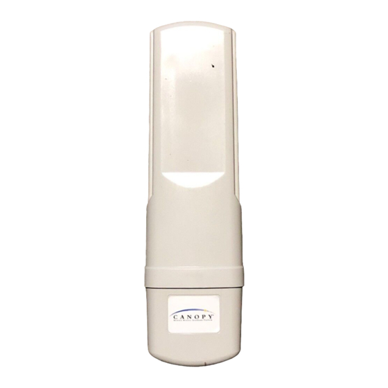
GETTING STARTED WELCOME Congratulations on the purchase of the Canopy subscriber module from Motorola! The Canopy subscriber module is the latest innovation in high-speed wireless networking that lets you easily network at high speeds. FEATURES The following is a subset of features included with your Canopy subscriber module: ♦... - Page 9 Remove the base cover as shown in FIGURE 1 to access the Ethernet connection and to view the LED indicators. • The RJ-45 connector is used to attach the Ethernet cable. • The LED’s indicate system status and can be used for alignment. FIGURE 2 SM User Manual Issue 2 Page 9 of 34...
- Page 10 The Connection LEDs report information about the current status of the subscriber module. following descriptions explain the function of each LED. Operational Mode When looking at the LEDs on the module the following descriptions go from left to right. LNK: The link LED displays the status of the Ethernet link to the Canopy module. The LED will be constantly lit if there is an Ethernet link present.
-
Page 11: Background Information On Networking
BACKGROUND INFORMATION ON NETWORKING Computers are assigned IP addresses by network operators, which have two methods available, static or dynamic IP addressing. The user of this document will need to understand how IP addressing is done at their particular location. All Canopy radio products (Subscriber Modules, Access Point Modules, and Backhaul Modules) have the default IP address of 169.254.1.1. -
Page 12: Installation
INSTALLATION The following steps are required to install the Canopy subscriber module. • Unpack the Canopy products • Configure the subscriber module for the Canopy network • Install the module • Align the module UNPACK THE CANOPY PRODUCTS Upon receipt, carefully inspect all shipping boxes for signs of damage. If there is damage, immediately notify the transportation company. -
Page 13: Installation Of The Subscriber Module
discern that a password is set. • The operator can enter in information about the Site Name, Location, and Contact. This is optional. If the subscriber module is in the 5.7 GHz band and the operator will be utilizing the Canopy passive reflector to obtain a link at distances of 10 miles or less, the subscriber module should be mounted to the reflector in the following manner. - Page 14 FIGURE 3 • Leave the unit mounting means loose enough to allow for movement when performing the alignment procedure. They must be tightened after the alignment procedure is completed. As with any such installed devices, the Canopy subscriber module and the Ethernet cable must be grounded in accordance with the latest revision of the National Electrical Code (NEC) and/or all country and local electrical codes to provide some protection against damage caused by near-miss lightning strikes and other electrical discharges.
-
Page 15: Align The Subscriber Module
Wiring Diagram of Canopy subscriber module to Computer with Surge Suppressor ALIGN THE SUBSCRIBER MODULE There are two methods that can be utilized for aligning a subscriber module to an access point module. The first is to monitor the RSSI and Jitter values on the subscriber. The second is to utilize the built-in alignment tool on the subscriber module. - Page 16 • Point subscriber module in direction of the access point. Remember that when utilizing the internal patch antenna the energy is radiated out in a 60° horizontal by 60° vertical pattern. IF UTILIZING A 5.7 GHz SUBSCRIBER MODULE: the passive reflector will change the radiated pattern to 6°...
-
Page 17: Cabling
CABLING The following information describes the wiring standards for installing a Canopy system. All diagrams use the EIA/TIA 568B color standard. Currently shipping modules auto-sense the Ethernet cable type – either RJ-45 straight-thru cable or RJ-45 crossover cable can be used to connect a network interface card (NIC), hub, router, or switch to a module. -
Page 18: Advanced Features
230 Guest login ok, access restrictions apply. 200 Type set to I 221 Goodbye The following is a sample telnet session: /---------\ C A N O P Y Motorola Broadband Wireless Technology Center (Copyright 2001, 2002 Motorola Inc.) Login: Password: password-if-configured Telnet+... - Page 19 Flash Web files /canopy.jpg 7867 free directory entries: 31 free file space: 56468 Telnet +> Telnet+ Flash Web files free directory entries: 32 free file space 64336 bytes...
-
Page 20: The Interface Screens
THE INTERFACE SCREENS The Canopy subscriber module contains a series of web pages that are used to interface to the unit. The following is a quick reference to interface screens. Note: These screens are subject to change by subsequent software versions. To access the web based interface you first must be on a computer that is in some way connected to the subscriber module. - Page 21 FPGA Version: displays the version of the FPGA (field programmable gate array) that is currently loaded into the module. Please make note of this information when obtaining technical support. Uptime: displays the length of time the module has been operating since a rest of the module occurred.
-
Page 22: Configuration
CONFIGURATION The Configuration webpage contains information and configurable parameters pertaining to the operation of the product. The first line of information on the Configuration screen is a repeat of the Device Type from the Status web page. The following are the parameters and their descriptions. Link Negotiation Speeds: choose the type of link speed desired for the Ethernet connection. - Page 23 is a means for the Canopy System operator to segregate an individual network or neighboring Canopy networks. Also, color code can be used to force a subscriber module to only register to a specific access point module even though the subscriber module may be able to see multiple access point modules.
- Page 24 Undo Save Changes: by clicking on this button, any changes that have been made and not committed through a reboot of the module will be undone.
- Page 25 Set to Factory Defaults: depressing this button will change all of the configurable parameters (all of which are contained on the Configuration page) back to their factory settings. Reboot: depressing this button will reboot the module. Canopy Default Plug When inserted, the default plug brings the module up with a default configuration. This allows the operator to regain control of a module, which may be using an IP address and/or password that has been forgotten.
-
Page 26: Event Log
EVENT LOG This page contains information that is recorded from the subscriber module for troubleshooting purposes. Please make note of the information that is gathered here when calling for technical support. Clear Event Log: this button will clear the event log. -
Page 27: Ap Eval Data
AP EVAL DATA The AP Eval Data web page contains information on each of the access point modules that the subscriber module has visibility to. For each access point module that can be seen certain bits of information are shown on this web page. An example of the information shown on this web page for each access point module: Index: 0 Frequency: 0 MHz ESN: 0a-00-3e-00-01-d5 Jitter: 5 RSSI:... -
Page 28: Ethernet Stats
ETHERNET STATS The Ethernet Stats web page reports TCP throughput and error information for the Ethernet connection of the subscriber module. The following definitions are available: inoctets count: displays the total number of octets received on the interface, including framing characters. -
Page 29: Expanded Stats
collision occurs during the first 512 bits of the frame transmission. If a collision occurs after the 512 bit times, then it is considered a late collision. A late collision should be taken as a serious network problem, since it causes the frame being transmitted to be discarded. The most common cause of late collisions is a mismatch between duplex configurations at each end of a link segment. -
Page 30: Alignment
The Link Test is a test for measuring the throughput and efficiency of the RF link between two Canopy modules. To perform a link test enter a number into the field labeled “ Duration ”. The duration is the number of seconds the RF link will be tested. -
Page 31: Ber Display
• Click “ Enable Aiming Mode ” The module will now report back the level of RF energy present at that specific frequency. To refresh the screen, click the Enable Aiming Mode button as appropriate or configure the web page auto-refresh option. -
Page 32: Accessories
Passive reflector dishes for use with 5.7 GHz subscriber modules (part number 27RD) • 90-230V AC power supply (part number ACPSSW-01) • Cable assemblies for the Canopy System can be ordered from Best-Tronics Manufacturing Inc. by going to their website at HTTP://WWW.BEST-TRONICS.COM/MOTOROLA... -
Page 33: Appendix
APPENDIX There are two basic concepts that are needed for a basic understanding of networking, IP addresses and subnet masks. IP addresses are 32-bit binary numbers that have two corresponding parts or sub-addresses, the first part identifying the network and the second part identifying the hosts on the network. -
Page 34: Specifications
SPECIFICATIONS Operating Frequency Range U-NII: 5.25 to 5.35 GHz and 5.725 to 5.825 GHz ISM (for Release 4.0): 5.725 to 5.850 GHz Access Method TDD/TDMA Signaling Rate 10 Mbps Modulation Type High Index BFSK (Optimized for interference rejection) Carrier to Interference (C/I) 3dB nominal also known as Jitter Receiver Sensitivity...
Need help?
Do you have a question about the 9000SM - Canopy 900 MHz Subscriber Module and is the answer not in the manual?
Questions and answers