Table of Contents
Advertisement
INSTALLATION AND
OWNER'S MANUAL
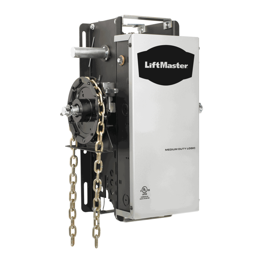
MJ5011S & MH5011S
MS SERIES JACKSHAFT COMMERCIAL VEHICULAR
As of date of manufacture,
meets all ANSI/UL 325
Safety Requirements
for
Vehicular door operators
DOOR OPERATORS
Serial #:
Date Installed:
Your Dealer:
READ THIS MANUAL
CAREFULLY BEFORE
INSTALLATION OR USE.
SAVE THIS MANUAL!
100771
Advertisement
Table of Contents

Subscribe to Our Youtube Channel
Related Manuals for Allstar MH5011S


Summary of Contents for Allstar MH5011S
- Page 1 INSTALLATION AND OWNER’S MANUAL MJ5011S & MH5011S MS SERIES JACKSHAFT COMMERCIAL VEHICULAR Serial #: Date Installed: Your Dealer: As of date of manufacture, meets all ANSI/UL 325 Safety Requirements Vehicular door operators DOOR OPERATORS READ THIS MANUAL CAREFULLY BEFORE INSTALLATION OR USE.
-
Page 2: Table Of Contents
TABLE OF CONTENTS Product Features ... 3 Jackshaft Operator Applications... 3 Preparation ...4 Figure 1 - Component Identification Pictorial... 4 Important Installation Warnings (Things To Do Before & During Installation) ... 5 Table 1 - Component Identification Listing... 5 Installation Instructions ...6-12 Figure 2 - Operator Footprint... -
Page 3: Product Features
The purpose of this booklet is to provide assembly, installation and operation information concerning Allstar Model MJ5011S & MH5011S (MS Series) Commercial Vehicular Garage Door Operators and related Accessory Products. NOTICE IT IS IMPORTANT THAT THIS INSTRUCTION MANUAL BE READ AND UNDERSTOOD COMPLETELY BEFORE INSTALLATION OR OPERATION IS ATTEMPTED. -
Page 4: Preparation
If the operator was ordered with the optional chain hoist, Model MH5011S, see that it is so equipped. A chain hoist CANNOT be added in the field. Warning:... -
Page 5: Installation Instructions
Check the door manufacturer’s instruction manual for a bracing procedure or the availability or a Reinforcement Kit. Allstar Model MJ5011S and MH5011S are ♦ Commercial Vehicular Door Operators and as such are NOT recommended for pedestrian traffic. -
Page 6: Installation Instructions
INSTALLATION INSTRUCTIONS SPRINGS, PULLEYS, CABLES AND MOUNTING HARDWARE USED TO BALANCE YOUR GARAGE DOOR ARE UNDER EXTREME TENSION AT ALL TIMES AND CAN CAUSE SEVERE INJURY OR DEATH IF DISTURBED. WARNING igure 4, page 7 illustrates several positions suitable for mounting the operator;... - Page 7 CHAIN HOIST AND FLOOR DISCONNECT INSTALLATION f the operator is furnished with a chain hoist (Model MH5011S), pass the hand chain over the chain wheel and through the chain guides on the operator clutch shaft (opposite end from the large pulley).
- Page 8 FIGURE 5 - OPERATOR DIMENSIONS - MODEL MJ5011S 100769 FIGURE 5A - OPERATOR DIMENSIONS - MODEL MH5011S 100771...
-
Page 9: Setting The Limits
WARNING TO AVOID RISK OF ENTRAPMENT AND POSSIBLE DAMAGE TO THE DOOR AND OPERATOR THE LIMITS MUST BE ADJUSTED BEFORE APPLYING POWER TO THE OPERATOR. SETTING THE LIMIT SWITCHES With the cover open on the electrical enclosure, reference Figure 6 below. There are two (2) switches (A and B) mounted to the ‘V’... -
Page 10: Figure 7 - Power Connections
INSTALLATION INSTRUCTIONS - ELECTRICAL WIRING WARNING TO PREVENT THE RISK OF PERSONAL INJURY OR DEATH : • DISCONNECT POWER AT THE FUSE BOX BEFORE PROCEEDING. • ELECTRICAL CONNECTIONS MUST BE MADE BY A QUALIFIED INDIVIDUAL. • OBSERVE LOCAL ELECTRICAL CODES WHEN WIRING THE OPERATOR. - Page 11 DOOR EDGE INSTALLATION & WIRING Figure 8 OPEN CLOSE STOP MOTOR CONTROL Figure 9 BOARD Door Edge and Photoelectric Wiring See text on page 10 for operation when Safe-Finish™ or Access Alliance Safe-Finish II™ photo-beams are connected. Note: When adding a SAFE FINISH PHOTOBEAM photocell device with a Normally Closed output...
-
Page 12: Installation Instructions
INSTALLATION INSTRUCTIONS MOTOR CONTROL BOARD OPEN CLOSE STOP Single 3 Button Station MOTOR CONTROL BOARD EXTERNAL INTERLOCK TURNING ON THE POWER TO THE OPERATOR NOTE: It is now necessary to turn on the power in order to to change the Operating Mode (if applicable), program any changes desired to the operator’s other settings, check for proper operation, and finalize any adjustments to include the limit settings. -
Page 13: Operation And Adjustment Instructions
IMPORTANT SAFETY INSTRUCTIONS FOR OWNER TO REDUCE THE RISK OF SEVERE INJURY OR WARNING DEATH: READ AND FOLLOW ALL INSTRUCTIONS! • Understand all of the operating features of your door control system at the time of its installation. Your installing dealer will demonstrate them for you. •... -
Page 14: Clutch Adjustment
OPERATION & ADJUSTMENT INSTRUCTIONS WARNING RISK OF ENTRAPMENT THAT MAY RESULT IN SERIOUS PERSONAL INJURY OR DEATH. DISCONNECT POWER TO THE OPENER BEFORE SERVICING OR MAKING ADJUSTMENTS. ENSURE DOORWAY IS CLEAR BEFORE STARTING TESTING OF UNIT. CAUTION ALWAYS DISCONNECT POWER TO OPERATOR BEFORE SERVICING OR MAKING ADJUSTMENTS. -
Page 15: Brake Adjustment
Brake Adjustment The brake is adjusted at the factory and may need periodic adjustment for wear. When adjustment becomes necessary see Figure 14 at right for the adjustment procedure. SETTING THE SWITCH SELECTABLE OPERATING MODES Changing the Switch Selectable Operation Modes The following modes are selected by setting the on-board dip switches, Figure 15 at right shows where the switches are located on the operator control board. - Page 16 OPERATION AND ADJUSTMENT INSTRUCTIONS B2 Operation Open Button: Momentary activation; open override of closing door. Close Button: Momentary activation. Stop Button: Momentary activation; stops open, close or reverse action. Single Button: Momentary activation to open; open override of closing door, closes door from mid-stop or open limit. Reverse: Momentary activation will reverse a closing door, reverse to full open (ignores mid-stop) unless stopped by stop pushbutton input.
-
Page 17: Setup Modes
Setup Modes Various operating characteristics can be modified via the setup modes. The operator is moved to the close limit position and the on-board dip switches (see Figure 15) are set according to the table at right to enter a Setup Mode. The on board OPEN and STOP buttons are used to modify the characteristic. -
Page 18: Operation And Adjustment Instructions
The door can then be manually opened or closed by physically moving the door (Model MJ5011S) or using the hoist chain (Model MH5011S). If it is difficult to engage and/or the jackshaft to doorshaft chain appears to be under compression, reset the CLOSE limit slightly to reduce the door travel in the close direction. -
Page 19: Wiring Diagram
BROWN GROUND LINE 24 VAC TRANSFORMER YELLOW YELLOW SAFE FINISH PHOTOBEAM 3-WIRE PHOTOBEAM WHITE GREY GREY ORANGE ORANGE BLUE YELLOW BLACK WHITE HIGH VOLTAGE POWER EDGE OPEN INTERLOCK WIRING DIAGRAM CLOSE LIMIT OPEN LIMIT OPERATING MODES STATUS SWITCH SETTING C2: OFF OFF OFF OFF B2: ON OFF OFF OFF D1: OFF ON OFF OFF E2: ON ON OFF OFF... -
Page 20: Warranty
NOTES Manufacturer’s Limited Warranty Linear LLC warrants its Allstar brand commercial door operators to be free from defect in material and workmanship for a period of two (2) years from the date of purchase. To obtain service contact your dealer. To obtain service under this warranty the buyer must obtain authorization instructions for the return of any goods from Linear before returning the goods.
Need help?
Do you have a question about the MH5011S and is the answer not in the manual?
Questions and answers