Table of Contents
Advertisement
Available languages
Available languages
Quick Links
IMPORTANT INSTRUCTIONS -
Models: P1030M, P1036M, P1830M,
P1836M, P1848M
READ AND SAVE THESE INSTRUCTIONS
READ CAREFULLY BEFORE ATTEMPTING TO ASSEMBLE, INSTALL, OPERATE OR MAINTAIN THE PRODUCT DESCRIBED.
PROTECT YOURSELF AND OTHERS BY OBSERVING ALL SAFETY INFORMATION. FAILURE TO COMPLY WITH
INSTRUCTIONS COULD RESULT IN PERSONAL INJURY AND/OR PROPERTY DAMAGE!
GENERAL SAFETY INFORMATION
electric shock and injury to person, including the following:
WARNING:
TO REDUCE THE RISK OF FIRE, ELECTRIC SHOCK
AND INJURY TO PERSON, OBSERVE THE FOLLOWING:
a) Use this unit only in the manner intended by the manufacturer.If you
have questions, contact the manufacturer.
b) Before servicing or cleaning the unit, switch power off at
service panel and lock the service disconnecting means to
prevent power from being switched on accidentally. When the
service disconnecting means cannot be locked, securely fasten
a prominent warning device, such as a tag, to the service panel.
WARNING:
TO REDUCE THE RISK OF FIRE, ELECTRIC SHOCK
AND INJURY TO PERSON, OBSERVE THE FOLLOWING:
a) Installation work and electrical wiring must be done by qualified
person(s) in accordance with all applicable codes and standards,
including fire-related construction.
b) Sufficient air is needed for proper combustion and exhausting
of gases through the flue (chimney) of fuel burning equipment to
prevent back drafting. Follow the heating equipment manufacturer's
guideline and safety standards such as those published by the
National Fire Protection Association (NFPA) and the American
Society for Heating, Refrigeration, and Air Conditioning Engineers
(ASHRAE), and the local code authorities.
c) When cutting or drilling into wall or ceiling, do not damage electrical
wiring and other hidden utilities.
CAUTION:
TO REDUCE THE RISK OF FIRE AND TO PROPERLY
EXHAUST AIR, BE SURE TO DUCT AIR OUTSIDE - DO NOT VENT
EXHAUST AIR INTO SPACES WITHIN WALLS OR CEILINGS OR INTO
ATTICS, CRAWL SPACES, OR GARAGES.
d) Ducted fans must always be vented to the outdoors.
e) This unit must be grounded.
f) To avoid motor bearing damage and noisy and/or unbalanced
impellers, keep drywall spray, construction dust, etc. off power unit.
g) Read all instructions before installing or using exhaust fan.
A111597011M New 8-10
OPERATING MANUAL
RETAIN INSTRUCTIONS FOR FUTURE REFERENCE.
When using electrical appliances, basic precautions
should always be followed to reduce the risk of fire,
SAVE THESE INSTRUCTIONS
WARNING:
NOT USE THIS FAN WITH ANY SOLID-STATE SPEED CONTROL DEVICE.
WARNING:
a) Never leave surface units unattended at high settings.
Boilovers cause smoking and greasy spillovers that may
ignite. Heat oils slowly on low or medium settings.
b) Always turn hood ON when cooking at high heat or when
flambéing food (ie. Crepes Suzette, Cherries Jubilee,
Peppercorn Beef Flambé).
c) Clean ventilating fans frequently. Grease should not be allowed
to accumulate on fan filter.
d) Use proper pan size. Always use cookware appropriate for
the size of the surface element.
WARNING:
THE EVENT OF A RANGE TOP GREASE FIRE, OBSERVE THE FOLLOWING:
a) SMOTHER FLAMES with a close-fitting lid, cookie sheet, or
metal tray, then turn off burner. BE CAREFUL TO PREVENT
BURNS. If the flames do not go out immediately, EVACUATE
AND CALL THE FIRE DEPARTMENT.
b) NEVER PICK UP A FLAMING PAN - You may be burned.
c) DO NOT USE WATER, including wet dishcloths or towels -
a violent steam explosion will result.
d) Use an extinguisher ONLY if:
I.
II. The fire is small and contained in the area where it started.
III. The fire department is being called.
IV. You can fight the fire with your back to an exit.
WARNING:
DUCTWORK.
www.airkinglimited.com
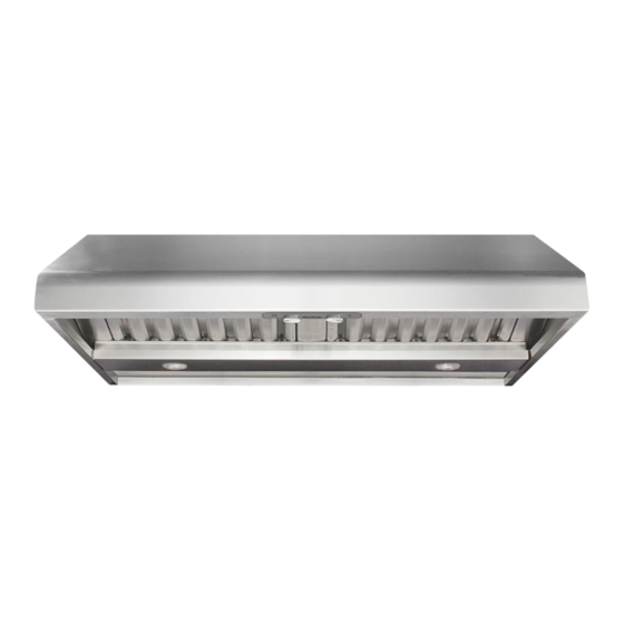
Outdoor Kitchen Professional
Range Hood Series
TO REDUCE THE RISK OF FIRE, ELECTRIC SHOCK, DO
TO REDUCE THE RISK OF A RANGE TOP GREASE FIRE:
TO REDUCE THE RISK OF INJURY TO PERSONS IN
You know you have a Class ABC extinguisher, and you
already know how to operate it.
TO REDUCE THE RISK OF FIRE, USE ONLY METAL
1 of 16
Advertisement
Table of Contents

Subscribe to Our Youtube Channel
Related Manuals for Air King P1030M


Summary of Contents for Air King P1030M
-
Page 1: General Safety Information
IMPORTANT INSTRUCTIONS - OPERATING MANUAL Outdoor Kitchen Professional Models: P1030M, P1036M, P1830M, P1836M, P1848M Range Hood Series READ AND SAVE THESE INSTRUCTIONS READ CAREFULLY BEFORE ATTEMPTING TO ASSEMBLE, INSTALL, OPERATE OR MAINTAIN THE PRODUCT DESCRIBED. PROTECT YOURSELF AND OTHERS BY OBSERVING ALL SAFETY INFORMATION. FAILURE TO COMPLY WITH INSTRUCTIONS COULD RESULT IN PERSONAL INJURY AND/OR PROPERTY DAMAGE! RETAIN INSTRUCTIONS FOR FUTURE REFERENCE. -
Page 2: Installation Instructions
INSTALLATION INSTRUCTIONS 1. The measurements for the installation will be custom to your specific location and will be dependent upon exact ceiling height, distance mounted from cooking surface, cabinet or soffit heights, along with other factors and will need to be adjusted CAUTION: MAKE SURE POWER IS SWITCHED OFF AT SERVICE PANEL accordingly. The hood must be mounted a minimum of 24” and a maximum of 36” BEFORE STARTING INSTALLATION. from the cooking surface (Figure 3). NOTE: Outdoor Kitchen Professional Range Hoods are approved for use in covered Ceiling outdoor kitchens only. Proper duct adapters, ducting, chimneys, roof/wall caps, etc. must be utilized as called out in the following instructions. Do not install the hood in an Soffits or Cabinet uncovered area directly exposed to the elements. SECTION 1 .75" Preparing the Range Hood Wood Mounting Strip 1. Unpack hood from the carton and confirm that all pieces are present. In addition to the range hood you should have: Hood 1 - Package containing: 3 - 2" wood screws... - Page 3 CAUTION: DUE TO THE WEIGHT OF THE HOOD, ENSURE THE WOOD STRIP Outlet Adapter IS FASTENED TO ALL AVAILABLE WALL STUDS (A MINIMUM OF 2 STUDS FOR 30” HOODS, MORE AS THE WIDTH INCREASES) NOT INTO THE DRYWALL ALONE. CAUTION: Screw SUPPORT THE HOOD UNTIL IT IS FULLY INSTALLED ONTO THE WOOD MOUNTING STRIP.
- Page 4 2. The thickness of the strips should be the same as the recess of the cabinet and NOTE: When determining the outlet adapter to be used, make sure to consider the clearance within the cabinet space. Typically a horizontal Outlet Adapter will need to they should be approximately 2” wide. be used if you will be venting out to a wall cap. 3. Install the strips using appropriate length wood screws (not included). Make sure the strips line up to the holes in the top of the canopy. NOTE: When the duct termination is similar to that shown in Figure 14 (passing through the wall to which the hood is mounted) the installation requires special consideration. 4. Mark the location where the outlet adapter (available separately) will be located Depending upon where the wall studs are located, it may be necessary to cut one or on the cabinets and cut a hole approximately 1” larger on all sides than the outlet more of the wall studs and install a header and footer to transfer the load to the adjacent adapter (Figure 12). studs. Additional studs may need to be framed into the opening to attach dry wall or secure the hood. If this is your situation Air King recommends that you hire a professional and comply with all applicable codes. 8. Install the proper sized outlet adapter (available separately) to the hood by sliding Hole it down into the hole cut earlier and matching up the four holes on the flange of the adapter to the four corresponding holes on the hood and secure in place with the provided screws. Ensure an airtight seal around the adapter by securing all connections with ducting tape (Figure 15). Outlet Adapter Figure 12 Screw NOTE: If the recommended, optional BS Series backsplash is being installed it must be installed before the hood canopy because the hood canopy will cover the backsplash mounting screws. Refer to the instructions included with the backsplash for complete Hood installation instructions. Flange 5. Rest the cavity in the back side of the hood on the wood strip and secure hood to wood strip with the included 3/4" screws through the holes in the back of the hood Cabinet...
-
Page 5: Blower Switch
Hot (Black) Channel Neutral Bottom (White) Supply from house Channel Ground (Green Figure 20 or Bare) SECTION 11 Figure 18 Operation Controls Your Range Hood is equipped with two rotary switches with one controlling the lighting SECTION 8 and the other controlling the exhaust fan blower. The light switch has three positions, High, Low, and Off. The fan switch has four positions, Off, High, Medium, and Low Installing the Blower (Figure 21). 1. Refer to the instructions included with the blower for installation. Light Switch SECTION 9 Installing the Optional Soffits Blower Switch 1. Refer to the instructions included with the specific soffit(s) you have chosen for Heat Lamp Switch installation. -
Page 6: Troubleshooting Guide
DATE OF ORIGINAL PURCHASE OR UNTIL THE ORIGINAL PURCHASER OF THE PRODUCT SELLS OR TRANSFERS THE PRODUCT, WHICHEVER FIRST OCCURS AND IN NO EVENT SHALL AIR KING’S LIABILITY UNDER ANY EXPRESS OR IMPLIED WARRANTY INCLUDE (I) INCIDENTAL OR CONSEQUENTIAL DAMAGES FROM ANY CAUSE WHATSOEVER, OR (II) REPLACMENT OR REPAIR OF ANY HOUSE FUSES, CIRCUIT BREAKERS OR RECEPTACLES. -
Page 7: Replacement Parts Diagram
REPLACEMENT PARTS DIAGRAM # Qty. Description Replacement Part # # Qty. Description Replacement Part # 1 1 Wire Box 5S1136064 12 1* Heat Lamp Holder 5S1136076 2 1 Wire Box Cover 5S1136065 13 ** Baffle Filter - PHGB1 5S1136077 3 1 Canopy 5S1136067 Baffle Filter - PHGB2 5S1136078... - Page 8 NOTES A111597011M New 8-10 www.airkinglimited.com 8 of 16...
-
Page 9: Instructions Générales De Sécurité
INSTRUCTIONS IMPORTANTES – MODE D’EMPLOI Série de hottes de cuisinières Modèles: P1030M, P1036M, P1830M, extérieures professionnelles P1836M, P1848M LIRE ET CONSERVER CES INSTRUCTIONS LIRE SOIGNEUSEMENT AVANT DE TENTER D’ASSEMBLER, INSTALLER, OPÉRER OU DE RÉPARER LE PRODUIT DÉCRIT. PROTÉGEZ VOUS-MÊME ET LES AUTRES EN OBSERVANT TOUTE L’INFORMATION DE SÉCURITÉ. FAILLIR À SE CONFORMER AUX INSTRUCTIONS PEUT RÉSULTER EN BLESSURE PERSONNELLE GRAVE ET/OU EN DOMMAGE À... - Page 10 INSTRUCTIONS D’INSTALLATION 1. Les mesures pour l’installation seront personnalisées à votre emplacement spécifique et dépendront de la hauteur exacte du plafond, de la distance de la surface de AVERTISSEMENT : cuisson, de la hauteur de l’armoire ou du soffite, ainsi que d’autres facteurs et VOUS ASSURER QUE L’ALIMENTATION EST doivent être ajustées en conséquence. La hotte doit être montée à un minimum de COUPÉE AU PANNEAU DE SERVICE AVANT DE COMMENCER L’INSTALLATION. 24 po et à un maximum de 36 po cm de la surface de cuisson (Figure 3). REMARQUE : Les hottes de cuisinières extérieures professionnelles sont approuvées Plafond pour l’usage dans les cuisines extérieures couvertes seulement. Vous devez utiliser Soffites ou armoire les adaptateurs de conduits, conduits, cheminées et clapets appropriés selon les instructions suivantes. N’installez pas la hotte dans un endroit découvert directement exposé aux éléments. .75 po SECTION 1 Bande de montage en bois Préparation de la hotte de cuisinière 1. Sortir la hotte de son emballage et confirmer que toutes les pièces sont présentes.
- Page 11 AVERTISSEMENT : EN RAISON DE LA HAUTEUR DE LA HOTTE, Adaptateur de ASSUREZ-VOUS QUE LA BANDE DE BOIS EST FIXEE A TOUS LES MONTANTS MURAUX DISPONIBLES (UN MINIMUM DE 2 MONTANTS POUR LES HOTTES DE sortie 30 PO, ET PLUS ALORS QUE LA LARGEUR AUGMENTE) ET NON PAS SEULEMENT DANS LA CLOISON SECHE.
- Page 12 2. L’épaisseur des bandes doit être la même que le retrait des armoires et elles REMARQUE : Lors de la détermination de l’adaptateur de sortie à utiliser, assurez-vous de doivent être d’une largeur d’environ 2 po. considérer le dégagement de l’espace de l’armoire. Typiquement, un adaptateur de sortie horizontale devra être utilisé si vous évacuez l’air par le biais d’une trappe murale. 3. Installez les bandes en utilisant des vis à bois de longueur appropriée (non-comprises). Assurez-vous que les bandes s’alignent avec les trous dans le dessus du couvert. REMARQUE : Lorsque la terminaison du conduit est similaire à celle illustrée à la Figure 4. Marquez l’emplacement où l’adaptateur de sortie (disponible séparément) sera 14 (passant au travers du mur sur lequel la hotte est installée) l’installation requiert une situé sur les armoires et coupez un trou de diamètre d’environ 1 po plus grand sur considération spéciale. Dépendant de où les montants muraux sont situés, il peut être tous les côtés que l’adaptateur de sortie (Figure 12). nécessaire de couper un montant mural ou plus et d’installer une chevêtre et une assise pour transférer la charge aux montants adjacents. Des montants additionnels pourraient devoir être bâtis dans l’ouverture pour fixer la cloison sèche et pour fixer la hotte. Si vous rencontrez cette situation, Air King recommande que vous embauchiez un professionnel et que vous vous conformiez avec tous les codes du bâtiment applicables. Trou 8. Installez l’adaptateur mural de la bonne taille requise (disponible séparément) à la hotte en le glissant dans les quatre trous percés précédemment sur la bride de l’adaptateur appariés aux quatre trous correspondants sur la hotte et fixez en place avec les vis comprises. Assurez-vous que le joint est étanche autour de l’adaptateur en sécurisant tous les raccords avec du ruban de gaine (Figure 15). Figure 12 Adaptateur de REMARQUE : Si le dosseret facultatif recommandé de la série BS est installé, il doit sortie être installé avant la verrière de la hotte parce que la verrière de la hotte couvrira les vis de support du dosseret. Référez-vous aux instructions incluses avec le dosseret pour des instructions d’installation complètes.
-
Page 13: Maintenance
Canal du Vivant (noir) haut Neutre (blanc) Canal du Alimentation provenant de la maison Terre (Vert Figure 20 ou nu) SECTION 11 Figure 18 Operation Contrôles YVotre hotte de cuisinière est équipée avec deux interrupteurs rotatifs dont l’un SECTION 8 contrôle l’éclairage et l’autre contrôle la soufflante du ventilateur d’évacuation. L’interrupteur de l’éclairage a 3 positions, Haute, Basse, et Éteinte. Le commutateur de Installation de la soufflante vitesse du ventilateur a quatre positions, Éteinte, Haute, Moyenne, et Basse (Figure 21). 1. Référez-vous aux instructions incluses avec le ventilateur pour l’installation. Interrupteur d’éclairage SECTION 9 Installation de soffites optionnels Interrupteur du ventilateur 1. Référez-vous aux instructions comprises avec le(s) soffite(s) spécifique(e) que Interrupteur de vous avez choisi pour l’installation. -
Page 14: Guide De Dépannage
AN DE LA DATE DE L'ACHAT ORIGINAL OU JUSQU'À CE QUE L'ACHETEUR ORIGINAL DU PRODUIT VEND OU TRANSFÈRE LE PRODUIT, CELUI QUI SE PRODUIT EN PREMIER ET DANS AUCUN CAS AIR KING N’ASSUME AUCUNE RESPONSABILITÉ EXPRESSE OU TACITE POUR (I) DES DOMMAGES ACCIDENTELS OU INDIRECTS DE N’IMPORTE QUELLE CAUSE, OU (II) LE REPLACEMENT OU LA RÉPARATION DE TOUS FUSIBLES, DISJONCTEURS OU RÉCEPTACLES DE MAISON. - Page 15 TABLEAU DES PIÈCES DE RECHANGE # de pièce # de pièce # Qté. Description de remplacement # Qté. Description de remplacement 1 1 Boîte de filage 5S1136064 12 1* Support pour lampe chauffante 5S1136076 2 1 Couvercle de la boîte de filage 5S1136065 13 ** Filtre déflecteur - PHGB1 5S1136077 3 1 Couvert 5S1136067...
- Page 16 REMARQUE A111597011M New 8-10 www.airkinglimited.com 16 of 16...
Need help?
Do you have a question about the P1030M and is the answer not in the manual?
Questions and answers