Table of Contents
Advertisement
Quick Links
Thank you for purchasing a Panasonic Projector.
Before operating this product, please read the instructions carefully and save this manual
J
for future use.
Before using your projector, be sure to read
J
Æ
(
pages 9 to 17).
M1010SW1011 -SA
Operating Instructions
DLP™ Based Projector
Model No.
Functional Manual
Commercial Use
PT-DZ570E
PT-DW530E
PT-DX500E
"Precautions with regard to safety"
TQBJ0350-1
ENGLISH
Advertisement
Chapters
Table of Contents

Related Manuals for Panasonic PT-DW530E


Summary of Contents for Panasonic PT-DW530E
-
Page 1: System Selector Yp B P R
PT-DZ570E Model No. PT-DW530E PT-DX500E Thank you for purchasing a Panasonic Projector. Before operating this product, please read the instructions carefully and save this manual for future use. Before using your projector, be sure to read “Precautions with regard to safety”... -
Page 2: Important Safety Notice
This instruction booklet provides all the necessary operating information that you might require. We hope it will help you to get the most out of your new product, and that you will be pleased with your Panasonic DLP™ Based projector. The serial number of your product may be found on its bottom. You should note it in the space provided below and retain this booklet in case service is required. - Page 3 Important Safety Notice Information for Users on Collection and Disposal of Old Equipment and used Batteries These symbols on the products, packaging, and/or accompanying documents mean that used electrical and electronic products and batteries should not be mixed with general household waste. For proper treatment, recovery and recycling of old products and used batteries, please take them to applicable collection points, in accordance with your national legislation and the Directives 2002/96/EC and 2006/66/EC.
- Page 4 Important Safety Notice IMPORTANT: THE MOULDED PLUG (U.K. only) FOR YOUR SAFETY, PLEASE READ THE FOLLOWING TEXT CAREFULLY. This appliance is supplied with a moulded three pin power plug for your safety and convenience. A 13 amp fuse is fitted in this plug. Should the fuse need to be replaced, please ensure that the replacement fuse has a rating of 13 amps and that it is approved by ASTA or BSI to BS1362.
- Page 5 Important Safety Notice Easy setup and Quick steps improved serviceability For details, see the corresponding pages. The dual-time zoom lens and the 1. Set up your projector. lens shift allow more flexible setup Æ page 23) of the projector. New lighting system with excellent dust resistance reduces the needs to replace filters as often (only 2.
-
Page 6: Table Of Contents
Contents Be sure to read “Precautions with regard to safety”. ( pages 9 to 17) Projecting ..........35 Important Information Selecting the input signal ........35 Important Safety Notice ......2 How to adjust the focus, zoom and shift ....35 Precautions with regard to safety .... 9 Adjustment range after lens position (optical shift) ..........36 WARNING ..............9... - Page 7 Contents KEYSTONE ............50 AUDIO SETTING ..........67 ADVANCED MENU ........51 STATUS ...............68 DATE AND TIME ..........68 DIGITAL CINEMA REALITY .........51 SAVE ALL USER DATA ........69 BLANKING ............51 LOAD ALL USER DATA ........69 INPUT RESOLUTION ..........52 INITIALIZE ............70 CLAMP POSITION ..........52 SERVICE PASSWORD ........70 FRAME RESPONSE ...........52 TEST PATTERN menu ......
- Page 8 Contents Specifications .......... 90 Dimensions ............92 About brand ............92 Ceiling mount bracket safeguards..93 Attachment procedure..........93 Cautions on Wireless LAN Module Installation ..........94 Procedure ............94 Index ............95 - ENGLISH...
-
Page 9: Precautions With Regard To Safety
Precautions with regard to safety WARNING POWER „ The wall outlet or the circuit breaker shall be installed near the equipment and shall be easily accessible when problems occur. If the following problems occur, cut off the power supply immediately. Continued use of the projector in these conditions will result in fire or electric shock. - Page 10 Precautions with regard to safety Do not place another projector or other heavy objects on top of the projector. Failure to observe this will cause the projector to become unbalanced and fall, which could result in damage or injury. The projector will be damaged or deformed. Installation work (such as ceiling suspension) should only be carried out by a qualified technician.
- Page 11 Precautions with regard to safety Do not allow children to reach the AA/R6/LR6 batteries. The battery can cause personal injury if swallowed. If swallowed, seek medical advice immediately. If the battery fluid leaks, do not touch it with bare hands, and take the following measures if necessary.
-
Page 12: Caution
Precautions with regard to safety CAUTION POWER „ When disconnecting the power cord, be sure to hold the power plug and power connector. If the power cord itself is pulled, the lead will become damaged, and fire, short-circuits or serious electric shocks will result. -
Page 13: Cautions When Installing
Precautions with regard to safety Cautions when installing Do not use under the following conditions. „ Do not set up the projector outdoors. The projector is designed for indoor use only. Avoid setting up in places which are subject to vibration or shocks. If the projector is installed in a place where vibrations are transmitted or mounted in a car or a vessel, vibrations or impacts will result in damage to the internal parts, causing failure. - Page 14 Precautions with regard to safety Cautions when setting the projectors 1 „ When installing and using the projector with a method other than floor standing installing using adjustable feet, fix it with the 4 ceiling mounting screws (shown in the figure). (Screw diameter: M4, Tapping depth inside set: 7 mm) When installing the projector with a method other than floor standing installing, do not adjust its angle with the adjustable feet.
-
Page 15: Security
Change your password regularly. Do not use a password that is simple to guess. Panasonic and its affiliate companies would never directly inquire about your password. Do not share your password with the general public. Set a password, and place restrictions on the users who can log in. -
Page 16: Cleaning And Maintenance
Precautions with regard to safety „ Do not touch the surface of the projector lens with your bare hand. If the surface of the lens becomes dirty from fingerprints or anything else, this will be magnified and projected onto the screen. Please put the lens cover on the projector when you do not use it. Do not move the projector while it is operating or subject it to vibration or „... -
Page 17: Accessories
Precautions with regard to safety Accessories Make sure the following accessories are provided with your projector. Remote control (x1) Power cord (x1) Power cord (x1) Drop-prevention bracket (x1) (N2QAYB000566) (TXFSX02RPLZ) (TXFSX03RPLZ) (TTRA0244) CD-ROM (x1) AA/R6/LR6 batteries for Lens cover (x1) (TXFQB02VKN9) remote control (x2) (TKKL5519) -
Page 18: Start-Up Display
Start-up display Start-up display The LANGUAGE and INITIAL SETTING menu will be displayed when the projector is turned on for the first time or after it has been initialized. Æ page 70) Navigate the DISPLAY OPTION menu to set the menus in accordance to its application and environment settings. Note When the projector is turned on for the first time, you may be required to adjust the “zoom ring”... -
Page 19: About Your Projector
About Your Projector Remote control Top view Installing/removing batteries Press the tab and lift up the Insert the batteries according to Remote control cover. the polarity diagram indicated signal emitters inside. (insert the side first). Remove the batteries in the reverse order to setting. -
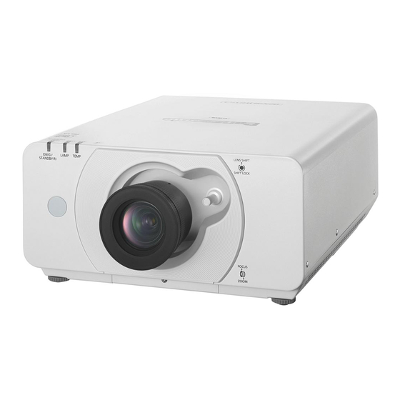
Page 20: Projector Body
Start-up display Projector body Front view Rear view Power indicator (STANDBY(R) / ON(G)) Indicates the power supply status Lamp indicator (LAMP) Indicates the lamp unit status. Temperature indicator (TEMP) Indicates the temperature status. Lens shift lever Front leg adjusters Screw up/down to adjust the projection Top view Bottom view angle. -
Page 21: Control Panel
Start-up display CONTROL PANEL <POWER ON> button ▲▼◄►button Switch between stand-by mode and projection mode. Use these buttons to select menu items, change settings, adjust levels, and to enter the [SECURITY] password. Switches to VIDEO or S-VIDEO input. <FUNCTION1> button Switches to RGB1 input. -
Page 22: Setting Projector Id Number To Remote Control
Start-up display Setting projector ID number to remote control Each projector can be assigned a unique ID number, and the handheld remote’ s number must be set to match the intended projector. The ID number of the projector is set to “ALL” on shipping, and use the ID ALL button of the remote control when using only a single projector. -
Page 23: Setting Up
Setting up Projection method You can use the projector with any of the following 4 projection methods. To set the desired method in the projector. Mounting on the ceiling and Setting on a desk/floor and projecting from front projecting from rear (Using translucent screen) Menu Method... -
Page 24: Screen Size And Throw Distance
Setting up Screen size and throw distance When planning the projector and screen geometry, refer to the figures below and the information on the following pages for reference. After the projector is roughly positioned, picture size and vertical picture positioning can be finely adjusted with the manual zoom lens and lens shifting mechanism. - Page 25 Setting up Projection distance for PT-DZ570E (All measurements below are approximate and may differ slightly from the actual measurements.) Projection size For 4:3 aspect ratio For 16:9 aspect ratio For 16:10 aspect ratio Minimum Maximum Minimum Maximum Minimum Maximum Screen diagonal (SD) distance distance distance...
- Page 26 Setting up Projection distance for PT-DW530E (All measurements below are approximate and may differ slightly from the actual measurements.) Projection size For 4:3 aspect ratio For 16:9 aspect ratio For 16:10 aspect ratio Minimum Maximum Minimum Maximum Minimum Maximum Screen diagonal (SD) distance distance distance...
- Page 27 Setting up Projection distance for PT-DX500E (All measurements below are approximate and may differ slightly from the actual measurements.) Projection size For 4:3 aspect ratio For 16:9 aspect ratio Minimum distance Maximum distance Minimum distance Maximum distance Screen diagonal (SD) (LW) (LT) (LW)
-
Page 28: Front Leg Adjusters And Throwing Angle
Setting up Front leg adjusters and throwing angle You can screw up/down the front leg adjusters to control the angle of the projector for adjusting the throwing angle. Adjustable range Front adjuster leg : 20 mm Attention Heated air comes out of the air exhaust port. Do not touch the air exhaust port directly. - ENGLISH... -
Page 29: Connections
Connections Before connection to the projector Read carefully the instruction manual for the device to be connected. Turning off the power switch of the devices before connecting cables. If any connection cable is not supplied with the device, or if no optional cable is available for connection of the device, prepare a necessary system connection cable to suit the device. -
Page 30: Connecting Example : Av Equipment
Connections Pin assignments and signal names of <DVI-D IN> terminal Pin No. Signal names Pin No. Signal names Outside view T.M.D.S data 2 - — T.M.D.S data 2+ T.M.D.S data 2/4 shield — Hot plug detection T.M.D.S data 0 - —... -
Page 31: Connecting Example : Computers
Connections Connecting example : Computers Control Computer Computer Computer Computer Audio system Control Computer Note The DVI-D signal input terminal supports only a single link. For the specifications of the RGB signals that can be applied from the PC, refer to “List of compatible signals”. -
Page 32: Powering On/Off
Powering ON/OFF Connecting the power cord Be sure to Insert the attached power cord securely to its base to prevent it from coming off. Before connecting the power cord, confirm that the MAIN POWER switch is in the “ ” (OFF) position. Installation Removal Insert the plug securely until its right... -
Page 33: Powering Up The Projector
Powering ON/OFF Powering up the projector Making adjustment and selection Connect the supplied power cable. (AC100-120 V 50-60 Hz) It is recommended that the images are projected continuously for at least 30 minutes before the focus Press the [ | ] marked side of the is adjusted. -
Page 34: Powering Off The Projector
Powering ON/OFF Powering off the projector Direct power off function Press POWER STANDBY ( The power supplied internally causes the cooling fan to continue operating and cool off in the event that Press ◄► to select [OK] and press the power has failed or even after the power cord is (ENTER). -
Page 35: English
Projecting Æ Check the connections of the peripheral devices, installation of the projection lens ( page 29), and connection Æ Æ of the power cord ( page 32) and switch on the power ( page 33) to start the projector. Select the input signal and adjust the image. -
Page 36: Adjustment Range After Lens Position (Optical Shift)
Projecting Adjustment range after lens position (optical shift) Do not move the lens beyond the bounds of the shift range as this may cause a change in the focus. This limitation is to protect the parts of the projector. Using the standard projection position as the reference, the optical axis shift function makes it possible to adjust the projection position in the ranges shown in the figures below. -
Page 37: Basic Operations Using The Remote Control
Basic operations using the remote control Switching the input signal You can use the remote control to switch the signals that are being input and projected. button Press <INPUT SELECT> button on the remote control or the main unit. RGB1 Switches to RGB1 input. -
Page 38: Automatic Adjustment
Basic operations using the remote control Automatic adjustment Using the function buttons The automatic setup function can be used to Three function buttons (<FUNCTION1 to 3>) on the automatically adjust the resolution, clock phase and remote control and the <FUNCTION1> button on the picture position when analog RGB signals consisting projector can be assigned to any frequent operations. -
Page 39: Controlling The Volume Of The Speaker
Basic operations using the remote control Controlling the volume of the speaker You can control the volume of output sound. button Press <VOLUME> button on the remote control. + button increases the volume - button decreases the volume ENGLISH -... -
Page 40: Menu Navigation
Menu Navigation Menus are extensively used for configuring, adjusting or reconfiguring the projector. Press ▲▼ button to highlight the Navigating through the menu desired adjustment item, then press ◄► to change or adjust the parameter Operating procedure value. Press <MENU> button. For some items, an individual adjustment screen [MAIN MENU] appears on the screen. -
Page 41: Main Menu
Menu Navigation MAIN MENU SUB MENU The main menu consists of the following 11 menu The sub-menu screen of the selected main menu items. appears, and you can set and adjust the various items When a main menu item is selected, the screen in the sub-menu. -
Page 42: Signal List
Menu Navigation TEST PATTERN [ DISPLAY LANGUAGE [ Æ Æ Details ( page 53) Details ( page 71) DISPLAY OPTION[ SIGNAL LIST [ Details ( Æ page 72) Sub-menu item Default Page SECURITY [ COLOR MATCHING COLOR CORRECTION Sub-menu item Default Page SCREEN SETTING... -
Page 43: Picture Menu
PICTURE menu Note “Navigating through the menu” Factory defaults are [GRAPHIC] for RGB system and Æ page 40). [STANDARD] for moving images. “MAIN MENU” and “SUB MENU” DICOM is an abbreviation for “Digital Imaging and Æ page 41). Communication in Medicine”, which is a standard for medical imaging devices. -
Page 44: Brightness
PICTURE menu BRIGHTNESS TINT You can adjust the brightness of the projected image. You can adjust the skin tone in the projected image. Press ▲▼ to select [BRIGHTNESS]. Press ▲▼ to select [TINT]. Press ◄► or <ENTER> button. Press ◄► or <ENTER> button. The [BRIGHTNESS] individual adjustment The [TINT] individual adjustment screen will be screen will be displayed. -
Page 45: White Gain
PICTURE menu Press <ENTER> button. Changing the name of [USER] The [WHITE BALANCE] screen will be Select [USER] in step 3). displayed. Press <ENTER> button. Press ▲▼ to select [WHITE BALANCE HIGH] or [WHITE The [COLOR TEMPERATURE] screen will be displayed. -
Page 46: Sharpness
PICTURE menu SHARPNESS This adjusts the sharpness of the pictures. Gray scale control is exercised to suit the images, and optimal images with a clear contrast are projected. Press ▲▼ to select [SHARPNESS]. Press ▲▼ to select [AI]. Press ◄► or <ENTER> button. Press ◄►... -
Page 47: System Selector
PICTURE menu HDMI terminal input signal SYSTEM SELECTOR 480p, 576p signals This enables the projector to automatically recognize Select from Auto, RGB, and YC input signals. Furthermore, if unstable signals are Other signals input, the system format can be selected manually. Select from Auto, RGB, and YP Press ▲▼... -
Page 48: Position Menu
POSITION menu ASPECT “Navigating through the menu” Æ page 40). This changes the aspect ratio of the projected image. “MAIN MENU” and “SUB MENU” This changes the aspect ratio for the screen range Æ page 41). selected with [SCREEN SETTING]. Set [SCREEN SETTING] first. -
Page 49: Zoom
POSITION menu VID AUTO (PRI.) Note Some size modes are not available for certain types of The projector identifies the abovementioned input signals. For NTSC signals, [DEFAULT] cannot be VID or S1 signals and displays the picture by selected. automatically choosing the screen sizes of 4 : 3 If an aspect ratio which is different from the aspect ratio or 16 : 9 according to the VID if it is detected or for the input signals is selected, the pictures will appear... -
Page 50: Clock Phase
POSITION menu Press ▲▼ to select [INTERLOCKED]. KEYSTONE Press ◄► to switch [INTERLOCKED]. If the projector is aligned non-perpendicularly to the The [VERTICAL] and screen, or if the projection screen has an angled [HORIZONTAL] settings are used surface, you can correct keystone. as the vertical and horizontal zoom Press ▲▼... -
Page 51: Advanced Menu
ADVANCED MENU BLANKING “Navigating through the menu” Æ page 40). Blanking adjustment fine-tunes the images projected “MAIN MENU” and “SUB MENU” by the video deck or other devices when the noise Æ page 41). appears on the edges of the screen or if a part of the image lies slightly offscreen. -
Page 52: Input Resolution
ADVANCED MENU INPUT RESOLUTION FRAME RESPONSE Input resolution adjustment achieves the best image When 1 080/60i, 1 080/50i or 1 080/24sF signals are when the screen flickers or halo is observed around entered, the video processing is simplified and the the contour. -
Page 53: Display Language Menu
DISPLAY LANGUAGE menu “Navigating through the menu” Æ page 40). “MAIN MENU” and “SUB MENU” Æ page 41). Changing the display language This lets you switch the on-screen display language. DISPLAY LANGUAGE Menus, setting items, adjustment screens, and control button names will be displayed in the language the user chooses. -
Page 54: Display Option Menu
DISPLAY OPTION menu Press <ENTER> button. “Navigating through the menu” The [3COLORS:RED], [3COLORS:GREEN] or Æ page 40). [3COLORS:BLUE] screen will be displayed. “MAIN MENU” and “SUB MENU” If you selected [7COLORS], the Æ page 41). [7COLORS:RED], [7COLORS:GREEN], [7COLORS:BLUE], [7COLORS:CYAN], [7COLORS:MAGENTA], [7COLORS:YELLOW], or [7COLORS:WHITE] screen will be displayed. -
Page 55: Color Correction
DISPLAY OPTION menu Use the colorimeter to measure If you have selected [USER] in the luminance (Y) and chromaticity step 2 coordinates (x, y) Press <ENTER> button. Press ▲▼ to select the colors, and The [COLOR CORRECTION] screen is press ◄► to select their values. displayed. -
Page 56: Waveform Monitor
DISPLAY OPTION menu Adjust the white level. WAVEFORM MONITOR In [CONTRAST] of on-screen menu [PICTURE], adjust the 100 % of the while level of the image (PT-DZ570E only) signal to the position corresponding to 100 % This function displays the waveform of the input signal on the waveform monitor. -
Page 57: Auto Setup
DISPLAY OPTION menu Adjusting the position AUTO SETUP automatically Use this setting when adjusting a specific or oblong Select [POSITION ADJUST] in step 3). (16:9, etc.) signal. Press ◄► to switch [POSITION Press ▲▼ to select [AUTO SETUP]. ADJUST]. Press <ENTER> button. The setting will change as follows each time The [AUTO SETUP] screen will be displayed. -
Page 58: Rgb In (Only Rgb Input)
DISPLAY OPTION menu Press ◄► to switch [DVI SIGNAL RGB IN (Only RGB input) LEVEL]. The setting will change as follows each time Change this setting to change the input impedance of ◄► is pressed. the synchronous signal input. Press ▲▼ to select [RGB IN]. 0-255 : PC 16-235 Press <ENTER>... -
Page 59: On-Screen Display
DISPLAY OPTION menu ON-SCREEN DISPLAY CLOSED CAPTION SETTING (for NTSC, 525i (480i) input only) The user can specify the on-screen display. Press ▲▼ to select [ON-SCREEN Set the closed caption display as follows. DISPLAY]. Press ▲▼ to select [CLOSED Press <ENTER> button. CAPTION SETTING]. -
Page 60: Back Color
Displaying the sub memory list area. and restoring the settings LOGO2 The Panasonic logo is projected. In the normal screen (when the menu Note is not displayed), press ◄► button. Separate software is required in order to create the The [SUB MEMORY LIST] screen will be pictures to use for [LOGO1]. -
Page 61: Freeze
DISPLAY OPTION menu FREEZE Turns Off the dual-screen projection. SIDE BY Select [SIDE BY SIDE OFF] in Step 4, SIDE OFF and press <ENTER> button. You can freeze the projected image and stop the sound temporarily, regardless of the playing condition Note of the connected device. - Page 62 DISPLAY OPTION menu [SIDE BY SIDE MODE] options MODE 1: Projects dual screens by fully using the horizontal size of each screen. The aspect ratio is held. The main and sub- screens have the same height. 16 : 9 4 : 3 The screens are centered in vertical direction.
-
Page 63: Projector Setup Menu
PROJECTOR SETUP menu Press ▲▼ to select [INSTALLATION]. “Navigating through the menu” Æ Press ◄► to switch [INSTALLATION]. page 40). “MAIN MENU” and “SUB MENU” The setting will change as follows each time Æ page 41). ◄► is pressed. FRONT/FLOOR FRONT/CEILING REAR/CEILING REAR/FLOOR... -
Page 64: High Altitude Mode
PROJECTOR SETUP menu HIGH ALTITUDE MODE ECO MANAGEMENT If you use the projector at high elevation (1 400 m to Can optimize lamp power and reduce the power 2 700 m), the [HIGH ALTITUDE MODE] setting needs consumption according to the application. to be [ON] to set the fan speed high. -
Page 65: Schedule
PROJECTOR SETUP menu NO SIGNAL SHUT-OFF SCHEDULE If no signal is input within a preset time, the projector This sets the command execution schedule for each power is automatically switched to the standby state. day of the week. Select [NO SIGNAL SHUT-OFF] in Step How to enable the SCHEDULE function Press ◄►... -
Page 66: Rs-232C
PROJECTOR SETUP menu Press ▲▼ to select [TIME] or RS-232C [COMMAND] and change the setting according to the instructions of the This sets the communication parameters at the serial menu. terminals. Press ▲▼ to select [RS-232C]. Set the time at which the command TIME Press <ENTER>... -
Page 67: Remote Mode
PROJECTOR SETUP menu REMOTE MODE AUDIO SETTING VOLUME You can customize the [REMOTE IN] terminal function. You can adjust the volume of the VARIABLE AUDIO Press ▲▼ to select [REMOTE MODE]. OUT terminal. ◄ Decrease Press ◄► to switch [REMOTE MODE]. ►... -
Page 68: Status
PROJECTOR SETUP menu STATUS POWER ON TIMES : Displays the number of times the power has been turned Displays the status of the projector. ON COUNT Press ▲▼ to select [STATUS]. LAMP ON : Press <ENTER> button. Displays the number of times LAMP has been lit. -
Page 69: Save All User Data
PROJECTOR SETUP menu Adjusting the date and time SAVE ALL USER DATA automatically This saves various setting values as a backup to the Press ▲▼ to select [DATE AND TIME]. internal memory of the projector. Press <ENTER> button. Press ▲▼ to select [SAVE ALL USER Press ▲▼... -
Page 70: Initialize
PROJECTOR SETUP menu INITIALIZE This returns various setting values to their factory default settings. Press ▲▼ to select [INITIALIZE]. Press <ENTER> button. The [SECURITY PASSWORD] screen will be displayed. Enter the password set for the [SECURITY PASSWORD]. The [INITIALIZE] screen will be displayed. Press ▲▼... -
Page 71: Test Pattern Menu
TEST PATTERN menu “Navigating through the menu” Æ page 40). “MAIN MENU” and “SUB MENU” Æ page 41). TEST PATTERN Results of adjustment of the position, size and other factors are not reflected in test patterns. Ensure the input signal is displayed before performing various kinds of setting. -
Page 72: Signal List Menu
SIGNAL LIST menu Renaming a registered data “Navigating through the menu” Æ page 40). Press ▲▼◄► to select the required “MAIN MENU” and “SUB MENU” Æ page 41). signal data. Press <ENTER> button. The [REGISTERED SIGNAL STATUS] screen will be displayed. Displays the character list. -
Page 73: Security Menu
SECURITY menu Note “Navigating through the menu” [PASSWORD] is set to [OFF] by default and when Æ page 40). initialized. “MAIN MENU” and “SUB MENU” Change the SECURITY PASSWORD regularly and make Æ page 41). it uneasy to guess. When you apply to the [SECURITY] menu The security password becomes valid when setting of before you change the password to your original, the security password is turned [ON] and then the MAIN... -
Page 74: Display Setting
SECURITY menu DISPLAY SETTING MENU LOCK You can set your original text, such as company You can lock <MENU> button function and the name or URL information, to display regularly on the password will be asked to display the menu every projected image while projecting. -
Page 75: Control Device Setup
SECURITY menu CONTROL DEVICE SETUP Control from the remote control and main unit controls can be restricted. Press ▲▼ to select [CONTROL DEVICE SETUP]. Press <ENTER> button. The [CONTROL DEVICE SETUP] screen will be displayed. Press ▲▼ to select [CONTROL PANEL] or [REMOTE CONTROLLER]. -
Page 76: Monitor Lamp Indicators
Monitor Lamp indicators Managing the indicated problems If a problem should occur with the projector, the indicators will inform you. Manage the indicated problems as follow. Attention Lamp indicator (LAMP) Power indicator Temperature indicator (TEMP) (STANDBY (R) / ON (G)) LAMP indicator Lamp Information... -
Page 77: Temp Indicator
Monitor Lamp indicators TEMP indicator Lamp Information Check point Remedial measure indication Wait about 5 minutes in the current Did you turn on the power when status. Warm-up status the ambient temperature was Install the unit in a location having lower than approx. -
Page 78: Replacement
Replacement Before replacing the unit Turn off the POWER switch of the projector in proper way and disconnect the power plug from the wall outlet. Æ pages 32, 34) Æ Be sure to observe the procedure “Powering off the projector” ( page 34) when performing power supply operation. -
Page 79: Air Filter
Replacement AIR FILTER Optional air filter (service part) is available from any Panasonic dealer. When you replace the projector lamp, replace the air filter at the same time. The replacement lamp unit (part number ET-LAD60A, 1 bulb unit) package contains one air filter (part number ET-LAD60A), but the ET-LAD60AW lamp unit (part number ET-LAD60AW, 2 bulb units) package contains two air filters (part number ET-LAD60AW). - Page 80 Replacement Use a Phillips screwdriver to loosen Open the “Exhaust Fan” as illustrated, the “Lamp unit cover fixing screw” and remove the “Air Filter” from “Air (3 screws) for the lamp unit to be filter housing". replaced until the screws turn freely. Hold the “Handle”...
-
Page 81: Troubleshooting
Troubleshooting Should any problem persist, contact your dealer. Reference Problem Cause page The power cord may not be connected. — The <MAIN POWER> switch is turned off. No electric supply is at the wall outlet. — Power does not turn The circuit breakers have tripped. - Page 82 Troubleshooting Reference Problem Cause page The cable may be longer than the optional cable. — The external video output from a laptop computer may not be correct. — Picture from a (You may be able to change the external output settings by pressing the computer does not [Fn] + [F3] or [Fn] + [F10] keys simultaneously.
-
Page 83: Technical Information
Technical Information Serial terminal The serial connector which is on the connector panel of the projector conforms to the RS-232C interface specification, so that the projector can be controlled by a personal computer which is connected to this connector. Connection Connecting terminals on projector Computer... -
Page 84: Basic Format
Technical Information Basic format Transmission from the computer begins with STX, then the ID, command, parameter, and ETX are sent in this order. Add parameters according to the details of control. (2 bytes) 2 ID Semicolon characters (1 byte) Colon (1 byte) (2 bytes) Start... -
Page 85: Cable Specifications
Technical Information Cable specifications <When connected to a computer> Computer (DTE Projector specifications) Control commands When controlling the projector from a computer, the following commands are available: <Projector control command> Command Control contents Notes Power [ON] To see if the power is [ON], use the [Power query] command. Power [OFF] Power query 000 = Standby... -
Page 86: Remote In Terminal
Technical Information REMOTE IN terminal Using the [REMOTE IN] terminal provided on the connection terminals of the main unit, it is possible to operate the projector from a control panel etc. furnished in a distant location where infrared remote control signal cannot be received. -
Page 87: Two Window Display Combination List (Pt-Dz570E/Pt-Dw530E)
Technical Information Two window display combination list (PT-DZ570E/PT-DW530E) RGB1 RGB2 DVI-D HDMI Subwindow VIDEO VIDEO Moving Moving NETWORK input input image system image system Main window input input input input system system RGB input RGB1 input RGB input RGB2 input VIDEO input S-VIDEO input Moving image... -
Page 88: List Of Compatible Signals
Technical Information List of compatible signals The following table specifies the types of signals compatible with the projector. Format : V = VIDEO, S = S-VIDEO, D = DVI, H : HDMI, R : RGB, Y : YP Scanning Dot clock frequency Display resolution Mode... - Page 89 Technical Information Scanning Dot clock frequency Display resolution Mode frequency Format (dots) DVI-D DVI-D DVI-D (MHz) RGB2 HDMI (kHz) (Hz) EDID1 EDID2 EDID3 1 280×800 41.3 50.0 68.0 D/H/R 1 280×800 49.7 59.8 83.5 D/H/R ○ ○ ○ ○ 1 280 × 800 1 280×800 49.3 59.9...
-
Page 90: Specifications
Optical output 4 000 lm (ANSI) 4 500 lm (ANSI) H : 15 kHz - 100 kHz, V : 24 Hz - 120 Hz PIAS (Panasonic Intelligent Auto Scanning) system For RGB signal Dot clock frequency Less than 162 MHz [480i] H: 15.75 kHz,... - Page 91 Specifications Model No. PT-DZ570E PT-DW530E PT-DX500E VIDEO IN 1 set, BNC, 1.0 V [p-p] 75 Ω S-VIDEO IN 1 set, Mini DIN 4-pin, Y: 1.0 V [p-p], C: 0.286 V [p-p] 75 Ω, compatible with S1 signal DVI-D IN 1 set, DVI-D 24-pin (Single link), DVI 1.0 compatible, HDCP compatible HDMI IN 1 set, HDMI 19-pin (HDCP/Deep color compatible) SERIAL IN...
-
Page 92: Dimensions
Specifications Dimensions <Unit : mm> 270 (10 5/8") 32 (1 1/8") 332 (13 1/16") About brand Trademark Acknowledgement Microsoft ® and its logos, Windows ® , Windows ® XP, Windows Vista ® , Windows ® 7, and Internet Explorer ® are the registered trademarks or trademarks of Microsoft Corporation in the United States and/or other countries. -
Page 93: Ceiling Mount Bracket Safeguards
Panasonic takes no responsibility for any losses or damage occurring as a result of using a ceiling mount bracket not manufactured by Panasonic, or if damage to the projector occurs as a result of an inappropriate location used for installing the ceiling mount bracket, even if the projector’s warranty period has not yet expired. -
Page 94: Cautions On Wireless Lan Module Installation
Cautions on Wireless LAN Module Installation Cautions on Wireless LAN Module Installation The optional Wireless LAN Module (part number ET-WM200E) is required to use wireless LAN functions. During installation, remove the cap from the Wireless LAN Module and mount the module in the projector. -
Page 95: Index
Index DVI-D IN .........58 Remote control .......19 REMOTE IN terminal ......86 About brand ........92 About Your Projector.......19 REMOTE MODE ......67 ECO MANAGEMENT .....64 Renaming a registered data ...72 Accessories ........17 Replacement ........78 Adjustment range after lens position Replacing the unit ......78 (optical shift) .......36 FRAME RESPONSE ......52 Restoring the MENU LOCK...