Table of Contents
Advertisement
Quick Links
Advertisement
Table of Contents

Related Manuals for Asus RS120-E4 - 0 MB RAM


Summary of Contents for Asus RS120-E4 - 0 MB RAM
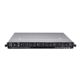
- Page 1 RS120-E4/PA4 1U Rackmount Barebone Server User Guide...
- Page 2 ASUSTeK COMPUTER INC. (“ASUS”). ASUS provides this manual “as is” without warranty of any kind, either express or implied, including but not limited to the implied warranties or conditions of merchantability or fitness for a particular purpose. In no...
-
Page 3: Table Of Contents
Contents Notices......................vii Safety.information..................viii About.this.guide..................ix Chapter.1:.Product.introduction 1.1. System.package.contents............1-2 1.2 System specifications..............1-3 1.3. Front.panel.features..............1-4 1.4. Rear.panel.features............... 1-4 1.5. Internal.features................1-5 1.6. LED.information................1-5 1.6.1 Rear panel LEDs ............. 1-5 1.6.2 Front panel LEDs ............1-6 1.6.3 LAN (RJ-45) LEDs ............ - Page 4 Chapter.5:.BIOS.setup 5.1. Managing.and.updating.your.BIOS..........5-2 5.1.1 Creating a bootable floppy disk ........5-2 5.1.2 AFUDOS utility ..............5-3 5.1.3 ASUS CrashFree BIOS 2 utility ........5-6 5.1.4 ASUS Update utility ............5-7 5.2. BIOS.setup.program..............5-10 5.2.1 BIOS menu screen ............5-11 5.2.2 Menu bar ................5-11...
- Page 5 Contents 5.3.4 IDE Configuration ............5-14 5.3.5 System Information ............5-17 5.4. Advanced.menu................5-19 5.4.1 CPU Configuration ............5-19 5.4.2 MPS Configuration ............5-20 5.4.3 Chipset Configuration ........... 5-21 5.4.4 PCI/PnP Configuration ..........5-25 5.4.5 USB Configuration ............5-26 5.4.6 Peripheral Devices Configuration .........
- Page 6 Contents 6.3.2 Creating a RAID 1 set (Mirror) ........6-34 6.3.3 Creating a RAID 10 set (Stripe + Mirror) ....... 6-35 6.3.4 Creating a RAID 5 set (Parity) ........6-36 6.3.5 Deleting a RAID set ............6-37 6.3.6 Resetting disks to Non-RAID ........6-38 ®...
-
Page 7: Notices
Notices Federal.Communications.Commission.Statement This device complies with Part 15 of the FCC Rules. Operation is subject to the following two conditions: • This device may not cause harmful interference, and • This device must accept any interference received including interference that may cause undesired operation. -
Page 8: Safety.information
Safety information Electrical.Safety • Before installing or removing signal cables, ensure that the power cables for the system unit and all attached devices are unplugged. • To prevent electrical shock hazard, disconnect the power cable from the electrical outlet before relocating the system. •... -
Page 9: About.this.guide
About this guide Audience This user guide is intended for system integrators, and experienced users with at least basic knowledge of configuring a server. Contents This guide contains the following parts: Chapter.1:.Product.Introduction This chapter describes the general features of the server, including sections on front panel and rear panel specifications. - Page 10 Refer to the following sources for additional information, and for product and software updates. ASUS.Server.Web-based.Management.(ASWM).user.guide This manual tells how to set up and use the proprietary ASUS server management utility. ASUS.websites The ASUS websites worldwide provide updated information for all ASUS...
- Page 11 Chapter 1 This chapter describes the general features of the chassis kit. It includes sections on front panel and rear panel specifications. ASUS RS120-E4/PA4...
-
Page 12: System.package.contents
ASUS R10 1U rackmount chassis with: • ASUS P5M2-R motherboard • 400 W power supply • SATA backplane (ASUS BP4LSA-F10-R10) with 4 x SATA cables • PCI-X and PCI Express x8 riser assembly (ASUS PCI64-EXP-X8) • Front I/O board (ASUS FPB-AR14) •... -
Page 13: System Specifications
1.2 System specifications The ASUS RS120-E4/PA4 is a 1U barebone server system featuring the ASUS ® P5M2-R motherboard. The server supports the Intel Xeon 3000 Series and Xeon X3200 Series processor in the LGA775 package, and includes the latest technologies through the chipsets embedded on the motherboard. -
Page 14: Front.panel.features
Front panel features The barebone server displays a simple yet stylish front panel with easily accessible features. The power and reset buttons, LED indicators, location switch, optical drive, and two USB ports are located on the front panel. Refer to section “1.6.2 Front panel LEDs” for the LED descriptions. Rack screw Rack screw Hot-swap HDD bays... -
Page 15: Internal.features
The barebone server does not include a floppy disk drive. Connect a USB floppy disk drive to any of the USB ports on the front or rear panel if you need to use a floppy disk. • Only ASUS CD/DVD-ROMs fit the optical drive bay. LED information 1.6.1. Rear.panel.LEDs... -
Page 16: Front Panel Leds
1.6.2. Front.panel.LEDs HDD Access LED Power LED Location LED LAN2 LED Message LED LAN1 LED Icon Display status Description System power ON Power LED No activity HDD Access LED Blinking Read/write data into the HDD System is normal; no incoming event Message LED Blinking ASWM indicates a HW monitor event... - Page 17 Chapter 2 This chapter lists the hardware setup procedures that you have to perform when installing or removing system components. ASUS RS120-E4/PA4...
-
Page 18: Chapter.2:.Hardware.setup
Chassis cover 2.1.1. Removing.the.front.cover Use a Phillips screwdriver to remove the screw on each front end of the top cover. Loosen the two thunbscrews on the rear panel to release the top cover from the chassis. Firmly hold the cover and slide it toward the rear panel for about half an inch until it is disengaged from the chassis. -
Page 19: Removing The Rear Cover
Disconnect the IDE cable and the power plug from the connectors on the back of the drive. Then leave the cover as side. 2.1.2. Removing.the.rear.cover Thumbscrews Loosen the two thumbscrews on the rear panel to release the top cover from the chassis. ASUS RS120-E4/PA4... -
Page 20: Installing The Cover
Firmly hold the cover and slide it toward the rear panel for about half an inch until it is disengaged from the chassis. 1/2 inch distance Lift the cover from the chassis. 2.1.3. Installing.the.top.cover Position the cover on top of the chassis with the thumbscrews on the rear, and leaving a gap of about half an inch from the front panel. -
Page 21: Central.processing.unit.(Cpu)
ASUS will shoulder the cost of repair only if the damage is shipment/transit-related. • Keep the cap after installing the motherboard. ASUS will process Return Merchandise Authorization (RMA) requests only if the motherboard comes with the cap on the LGA775 socket. - Page 22 Press the load lever with your thumb (A), then move it to the left (B) until it is released from the retention tab. Retention tab PnP cap Load lever This side of the socket box should face you. To prevent damage to the socket pins, do not remove the PnP cap unless you are installing a CPU.
-
Page 23: Installing The Cpu Heatsink And Airduct
CPU. Twist each of the four screws with a Philips (cross) screwdriver just enough to attach the heatsink to the motherboard. When the four screws are attached, tighten them one by one to completely secure the heatsink. ASUS RS120-E4/PA4... - Page 24 To install the airduct: Position the airduct on top of the heatsink. Carefully lower the airduct until it fits in place. Chapter 2: Hardware setup...
-
Page 25: System.memory
• Always install DIMMs with the same CAS latency. For optimum compatibility, it is recommended that you obtain memory modules from the same vendor. Visit the ASUS website for an updated DDR2 Qualified Vendors List for this motherboard. • Due to chipset resource allocation, and depending on the number of... -
Page 26: Installing A Dimm
2.3.3. Installing.a.DIMM Make sure to unplug the power supply before adding or removing DIMMs or other system components. Failure to do so may cause severe damage to both the motherboard and the components. To install a DIMM: DDR2 DIMM notch Unlock a DIMM socket by pressing the retaining clips outward. -
Page 27: Hard.disk.drives
Each side has three holes to fit different types of hard disk drives. Use two screws on each side to secure the hard disk drive. Place a SATA hard disk drive on the tray, then secure it with four screws. ASUS RS120-E4/PA4 2-11... - Page 28 Carefully insert the drive tray and push it all the way to the depth of the bay until just a small fraction of the tray edge protrudes. When installed, the SATA connector on the drive connects to the SATA interface on the backplane.
-
Page 29: Expansion.slot
Place the riser card bracket on a flat and stable surface, then remove the screw from the PCI-X slot bay. PCI-X slot Install a PCI-X card to the bracket as shown, then secure the card with a screw. ASUS RS120-E4/PA4 2-13... - Page 30 To install a PCI Express x8 card: Follow steps 1 to 2 of the previous section. PCI Express x8 slot Use a Phillips (cross) screwdriver to remove the screw that secures the slot metal cover. Remove the slot metal cover, then set it aside.
-
Page 31: Reinstalling The Riser Card Bracket
8 a n d P C I - X s l o t s o n t h e motherboard. Press the riser card bracket until the golden connectors completely fit the slot and the bracket aligns with the rear panel. Connect the cable(s) to the card, if applicable. ASUS RS120-E4/PA4 2-15... -
Page 32: Configuring An Expansion Card
2.5.3 Configuring an expansion.card After installing the expansion card, configure the it by adjusting the software settings. Turn on the system and change the necessary BIOS settings, if any. See Chapter 5 for information on BIOS setup. Assign an IRQ to the card. Refer to the following tables. Install the software drivers for the expansion card. -
Page 33: Cable.connections
Panel connector (from motherboard to front I/O board) See page 4-17. Auxiliary panel connector (from motherboard to front I/O board) See page 4-16. 10. USB connector (from motherboard to front I/O board) 11. FRNT_FAN4 connector (from motherboard to FAN_IN connector on SATA backplane) ASUS RS120-E4/PA4 2-17... -
Page 34: Sata.backplane.cabling
SATA backplane cabling FAN_IN1 connects the fan cable Connects the device fan cable from FRNT_FAN4 on the MB Connects the device fan cable Connects the SATA cable from Connects a 8-pin plug from SATA4 (Port3) on the MB power supply Connects the SATA cable from SATA3 (Port2) on the MB Connects the SATA cable from... -
Page 35: Removable.components
Refer to the illustration below for location of the system fans. 56 mm * 40 mm system fans 28 mm * 40 mm fan Incorrect installation of the system fan with dummy case may result to CPU overheating and/or automatic system shutdown. ASUS RS120-E4/PA4 2-19... - Page 36 To uninstall the system fans: Disconnect a system fan cable from the fan connector on the backplane board. Lift the fan, then set aside. Repeat step 1 to 2 to uninstall the other system fans. To reinstall the system fan: Insert the fan to the fan cage.
-
Page 37: System Fan With Dummy Case
Turn the dummy case to the direction of the arrow. Insert the dummy case pegs to the system fan holes until it fits in place. Reinstall the system fan by following the instructions in the previous section. ASUS RS120-E4/PA4 2-21... -
Page 38: Device Fan
2.8.3. Device.fan The system comes with two 28 mm * 40 mm (15500 rpm) device fans. Refer to the illustration below for location of the device fans. 28 mm * 40 mm device fans To uninstall the device fan: Disconnect the device fan cable from the connector on the motherboard or backplane board. -
Page 39: Power Supply Module
From the rear panel, remove two screws that secure the power supply from the chassis. Slide the power supply forward for about half an inch, then carefully lift it out from the chassis. ASUS RS120-E4/PA4 2-23... -
Page 40: Optical Drive
2.8.5. Optical.drive To uninstall the slim optical drive: Use a Phillips screwdriver (cross) to remove the screw on each end of the top cover. Loosen the two thunbscrews on the rear panel to release the top cover from the chassis. Firmly hold the cover and slide it toward the rear panel for about half an inch until it is disengaged from... - Page 41 Locator LED cable and USB cable from the connectors under the top front cover. Disconnect the IDE cable and the power plug from the connectors on the back of the drive. Then leave the cover as side. ASUS RS120-E4/PA4 2-25...
- Page 42 Use a Phillips screwdriver (cross) to remove three screws that secures the drive. 10. Use a Phillips screw driver (cross) to remove two screws that secures the backplane with the drive. Then, remove the backplane from the drive. 11. Carefully slide the optical drive inward for about half an inch, then lift it out of the bay.
-
Page 43: Motherboard
Use a Philips (cross) screwdriver to remove the screws that secure the motherboard to the base of the chassis. Refer to the illustration below for the location of the motherboard screws. ® P5M2-R Carefully lift the motherboard out of the chassis as shown. ASUS RS120-E4/PA4 2-27... - Page 44 To reinstall the motherboard: Firmly hold the motherboard by the sides and insert it into the chassis as shown. Carefully adjust the motherboard until the rear panel ports fit in place. Use a Phillips (cross) screwdriver to secure the motherboard with ten (10) screws in the holes as shown in the illustration in the previous section.
- Page 45 Chapter 3 This chapter describes how to install the optional components and devices into the barebone server. ASUS RS120-E4/PA4...
-
Page 46: Chapter.3:.Installation.options
3.1. Rackmount.rail.kit.items If you have the rackmount rail kit, it contains two pairs of rails (one pair for each side of the barebone system), and eight (8) pairs of nut-and-bolt type screws. Nuts Bolts Left pair Right pair 3.2. Rack.rails.assembly To assemble the rack rails: Determine the depth of the rack where you wish to install the system. -
Page 47: Attaching.the.rails.to.the.rack
Drive in two screws on the outer holes to secure the rear end. From the rack front, find the corresponding 1U space for the second rail pair. Repeat steps 2 to 7 to attach the second rail pair. When properly installed, the rack rails appear as shown. ASUS RS120-E4/PA4... -
Page 48: Rackmounting.the.server
3.4. Rackmounting.the.server To mount the server to the rack: Firmly hold the server on both sides and insert the rear panel side to the front end of the rack rail, then carefully push the server all the way to the back until the front panel fits the front end of the rack, and the rack screws on the server match the middle hole on the rack.. - Page 49 Chapter 4 This chapter includes the motherboard layout, and brief descriptions of the jumpers and internal connectors. ASUS RS120-E4/PA4...
-
Page 50: Chapter.4:.Motherboard.information
4.1. Motherboard.layout 31cm (12.2in) VGA1 COM1 PS2_MS1 PS2_KB1 USB2 USB1 LAN2 LAN1 LOCSW1 KBPWR1 USBPW12 SB_PWR1 TPM1 Broadcom Broadcom BCM5721 BCM5721 LAN_EN2 BMCSOCKET1 ® P5M2-R ES1000 Intel ® E3000 ® Intel 6702 CR2032 3V PXH-V Lithium Cell CMOS Power ® Intel ICH7R RAID_SEL1... - Page 51 SSI power connectors (24-pin ATXPWR1, 4-pin ATX12V1) 4-13 Printer port connector (26-1 pin LPT1) 4-14 TPM connector (20-1 pin TPM1) 4-14 Backplane SMBus connector (6-1 pin BPSMB1) 4-15 Auxiliary panel connector (20-pin AUX_PANEL1) 4-16 System panel connector (20-pin PANEL1) 4-17 ASUS RS120-E4/PA4...
-
Page 52: Jumpers
4.2. Jumpers Clear.RTC.RAM.(CLRTC1) This jumper allows you to clear the Real Time Clock (RTC) RAM in CMOS. You can clear the CMOS memory of date, time, and system setup parameters by erasing the CMOS RTC RAM data. The onboard button cell battery powers the RAM data in CMOS, which includes system setup information such as system passwords. - Page 53 (the default is the Space Bar). This feature requires an ATX power supply that can supply at least 1A on the +5VSB lead, and a corresponding setting in the BIOS. KBPWR1 ® P5M2-R +5VSB (Default) P5M2-R.Keyboard.power.setting ASUS RS120-E4/PA4...
- Page 54 Gigabit.LAN1.controller.setting.(3-pin.LAN_EN1) ® This jumper allows you to enable or disable the Broadcom Gigabit LAN controller that controls the LAN1 port. Place a jumper cap on pins 1-2 to activate the Gigabit LAN1 controller. LAN_EN1 ® P5M2-R Enable Disable (Default) P5M2-R.Gigabit.LAN1.setting Gigabit.LAN2.controller.setting.(3-pin.LAN_EN2) ®...
- Page 55 Place the jumper cap over pins 1-2 if you want to use the LSI Logic Embedded SATA RAID Utility (default); otherwise, place the ® jumper cap to pins 2-3 to use the Intel Matrix Storage Manager utility. ® P5M2-R RAID_SEL1 LSI RAID ROM INTEL RAID ROM P5M2-R.RAID.select.jumper (Default) ASUS RS120-E4/PA4...
- Page 56 Force.BIOS.recovery.(3-pin.RECOVERY1) This jumper allows you to update or recover the BIOS settings when it gets corrupted or destroyed.This jumper allows you to update/recover the BIOS quickly. To update the BIOS: Prepare a CD-ROM that contains the original or latest BIOS for the motherboard (P5M2R.ROM) and the AFUDOS.EXE utility.
-
Page 57: Connectors
Pin 20 on the IDE connectors is removed to match the covered hole on the Ultra ATA cable connector. This prevents incorrect insertion when you connect the IDE cable. ® P5M2-R PRI_IDE1 PIN 1 NOTE:.Orient the red markings (usually zigzag) on the IDE ribbon cable to PIN 1. P5M2-R.IDE.connector ASUS RS120-E4/PA4... - Page 58 Serial.ATA.connectors.(7-pin.SATA1,.SATA2,.SATA3,.SATA4) These connectors are for the Serial ATA signal cables for Serial ATA hard disk drives. If you installed Serial ATA hard disk drives, you can create a RAID 0 and ® RAID 1 configuration using the Intel Matrix Storage Manager, or RAID 0, and RAID 1 configuration using the LSI Logic Embedded SATA RAID utility in the ®...
- Page 59 These are not jumpers! Do not place jumper caps on the fan connectors! REAR_FAN1 REAR_FAN2 FAN Power FAN Power FAN Speed FAN Speed PWM Control PWM Control ® FRNT_FAN1 FRNT_FAN2 P5M2-R FRNT_FAN3 FRNT_FAN4 P5M2-R.Fan.connectors ASUS RS120-E4/PA4 4-11...
- Page 60 USB.port.connector.(10-1.pin.USB34) By default this connects to the front panel to support two USB 2.0 ports. ® P5M2-R USB34 USB _P4+ USB_P3+ USB_P4- USB_P3- USB+5V USB+5V P5M2-R.USB.2.0.connectors Serial.port.connector.(10-1.pin.COM2) This connector is for a serial (COM) port. Connect the serial port module cable to this connector, then install the module to a slot opening at the back of the system chassis.
- Page 61 +5V Standby +5 Volts Power OK -5 Volts ® P5M2-R Ground Ground +5 Volts Ground Ground Ground +5 Volts PSON# Ground Ground +3 Volts -12 Volts +3 Volts +3 Volts GND +12V DC ATX12V1 P5M2-R.ATX.power.connectors GND +12V DC ASUS RS120-E4/PA4 4-13...
- Page 62 Printer.port.connector.(26-1.pin.LPT1) This connector is for a parallel printer port. Connect the parallel printer port module cable to this connector, then install the module to a slot opening at the back of the system chassis.s LPT1 ® Pin 1 P5M2-R STB# AFD# SPD0 ERROR#...
- Page 63 11.. Backplane.SMBus.connector.(6-1.pin.BPSMB1) This connector allows you to connect SMBus (System Management Bus) devices. Devices communicate with an SMBus host and/or other SMBus devices using the SMBus interface. ® P5M2-R BPSMB1 HWM_FANOUT I2C_6_CLK# I2C_6_DATA# P5M2-R.SMBus.connector ASUS RS120-E4/PA4 4-15...
- Page 64 12.. Auxiliary.panel.connector.(20-pin.AUX_PANEL1) This connector is for additional front panel features including front panel SMB, locator LED and switch, chassis intrusion, and LAN LEDs. •. Front.panel.SMB.(6-1.pin.FPSMB) These leads connect the front panel SMBus cable. •. LAN..activity.LED.(2-pin.LAN1_LED,.LAN2_LED) These leads are for Gigabit LAN activity LEDs on the front panel. •.
- Page 65 BIOS settings. Pressing the power switch for more than four seconds while the system is ON turns the system OFF. •. Reset.button.(Blue.2-pin.RESET) This 2-pin connector is for the chassis-mounted reset button for system reboot without turning off the system power. ASUS RS120-E4/PA4 4-17...
- Page 66 4-18 Chapter 4: Motherboard information...
- Page 67 Chapter 5 This chapter tells how to change the system settings through the BIOS Setup menus. Detailed descriptions of the BIOS parameters are also provided. ASUS RS120-E4/PA4...
-
Page 68: Chapter.5:.Bios.setup
Managing.and.updating.your.BIOS The following utilities allow you to manage and update the motherboard Basic Input/Output System (BIOS) setup. ASUS.AFUDOS (Updates the BIOS in DOS mode using a bootable floppy disk.) ASUS.CrashFree.BIOS.2 (Updates the BIOS using a bootable floppy disk or the motherboard support CD when the BIOS file fails or gets corrupted.) ®... -
Page 69: Afudos Utility
Extension name Press <Enter>. The utility copies the current BIOS file to the floppy disk. A:\>afudos /oOLDBIOS1.rom AMI Firmware Update Utility - Version 1.19(ASUS V2.07(03.11.24BB)) Copyright (C) 2002 American Megatrends, Inc. All rights reserved. Reading flash ..done Write to file..ok A:\>... - Page 70 Updating the BIOS file To update the BIOS file using the AFUDOS utility: Visit the ASUS website (www.asus.com) and download the latest BIOS file for the motherboard. Save the BIOS file to a bootable floppy disk. Write the BIOS filename on a piece of paper. You need to type the exact BIOS filename at the DOS prompt.
- Page 71 The utility returns to the DOS prompt after the BIOS update process is completed. Reboot the system from the hard disk drive. A:\>afudos /i8036A0.ROM AMI Firmware Update Utility - Version 1.19(ASUS V2.07(03.11.24BB)) Copyright (C) 2002 American Megatrends, Inc. All rights reserved. WARNING!! Do not turn off power during flash BIOS Reading file ..
-
Page 72: Asus Crashfree Bios 2 Utility
5.1.3. ASUS.CrashFree.BIOS.2.utility The ASUS CrashFree BIOS 2 is an auto recovery tool that allows you to restore the BIOS file when it fails or gets corrupted during the updating process. You can update a corrupted BIOS file using the motherboard support CD that contains the updated BIOS file. -
Page 73: Asus Update Utility
5.1.4. ASUS.Update.utility The ASUS Update is a utility that allows you to manage, save, and update the ® motherboard BIOS in Windows environment. The ASUS Update utility allows you • Save the current BIOS file • Download the latest BIOS file from the Internet •... - Page 74 To update the BIOS through the Internet: ® Launch the ASUS Update utility from the Windows desktop by clicking Start > Programs > ASUS > ASUSUpdate > ASUSUpdate. The ASUS Update main window appears. Select Update.BIOS from the Select the ASUS FTP site nearest...
- Page 75 To update the BIOS through a BIOS file: ® Launch the ASUS Update utility from the Windows desktop by clicking Start > Programs > ASUS > ASUSUpdate > ASUSUpdate. The ASUS Update main window appears. Select Update BIOS from a file option from the drop-down menu, then click Next.
-
Page 76: Bios.setup.program
The BIOS setup screens shown in this section are for reference purposes only, and may not exactly match what you see on your screen. • Visit the ASUS website (www.asus.com) to download the latest BIOS file for this motherboard. 5-10... -
Page 77: Bios Menu Screen
At the bottom right corner of a menu screen are the navigation keys for that particular menu. Use the navigation keys to select items in the menu and change the settings. Some of the navigation keys differ from one screen to another. ASUS RS120-E4/PA4 5-11... -
Page 78: Menu Items
5.2.4. Menu.items The highlighted item on the menu bar BIOS SETUP UTILITY Main Advanced Server Security Boot Exit displays the specific items for that menu. Use [ENTER], [TAB], System Date [Sun 02/12/2006] or [SHIFT-TAB] to select a field. System Time [11:10:19] For example, selecting Main shows the Use [+] or [-] to... -
Page 79: Main.menu
System.Time.[xx:xx:xx] Allows you to set the system time. 5.3.3. Legacy.Diskette.A.[Disabled] Sets the type of floppy drive installed. Configuration options: [Disabled] [360K, 5.25 in.] [1.2M , 5.25 in.] [720K , 3.5 in.] [1.44M, 3.5 in.] [2.88M, 3.5 in.] ASUS RS120-E4/PA4 5-13... -
Page 80: Ide Configuration
5.3.4. IDE Configuration The items in this menu allow you to set or change the configurations for the IDE devices installed in the system. Select an item then press <Enter> if you want to configure the item. BIOS SETUP UTILITY Main IDE Configuration Options ATA/IDE Configuration... - Page 81 • [PATA Pri, SATA Sec] - SATA2 and SATA4 ports are available • [SATA Pri, PATA Sec] - SATA1 and SATA3 ports are available • [PATA Only] - Only PATA ports are available The Legacy.IDE.Channels option appears only when you set the ATA/IDE. Configuration item to [Compatible] mode. ASUS RS120-E4/PA4 5-15...
- Page 82 Primary/Tertiary/Fourth.IDE.Master/Slave The BIOS automatically detects the connected IDE devices. There is a separate sub-menu for each IDE device. Select a device item, then press <Enter> to display the IDE device information. BIOS SETUP UTILITY Main Primary IDE Master Select the type of device connected to Device : Hard Disk...
-
Page 83: System Information
General Help F10 Save and Exit ESC Exit v02.58 (C)Copyright 1985-2006, American Megatrends, Inc. The items in this menu are non-user configurable. Model.Name/Model.ID Displays the ASUS internal model information. ASUS.BIOS Displays the BIOS revision and build date. ASUS RS120-E4/PA4 5-17... - Page 84 Processor Information Displays the auto-detected CPU specification. BIOS SETUP UTILITY Main Processor Information *** CPU1 : Brand Genuine Intel(R) CPU 3.00GHz ID/uCode 0F64h/02h Speed 3.000GHz Ratio Actual 15 Max 15 Cache L1/16 KB L2/2048 KB Select Screen Select Item Change Option General Help F10 Save and Exit ESC Exit...
-
Page 85: Advanced.menu
Intel(R) C-State tech. ESC Exit C1 Config. [Enhanced] v02.58 (C)Copyright 1985-2004, American Megatrends, Inc. Max.CPUID.Value.Limit.[Disabled] Setting this item to [Enabled] allows legacy operating systems to boot even without support for CPUs with extended CPUID functions. Configuration options: [Disabled] [Enabled] ASUS RS120-E4/PA4 5-19... -
Page 86: Mps Configuration
Virtualization.Technology.[Enabled] Enable this item when the processor supports this feature. Reset to change its state. Configuration options: [Enabled] [Disabled] Execute.Disable.Bit.[Enabled] When this item is set to [Disabled], the BIOS forces the XD feature flag to always return to (0). Configuration options: [Enabled] [Disabled] The Hyper-Threading Technology item appears only when you installed an ®... -
Page 87: Chipset Configuration
Allows you to remap the overlap PCI memory over the total physical memory. Configuration options: [Disabled] [Enabled] DRAM Frequency [Auto] Allows you to set the DDR operating frequency. Configuration options: [Auto] [533 MHz] [667 MHz] The DRAM.Frequency item becomes configurable when Configure DRAM Timing.by.SPD item is set to [Disabled] ASUS RS120-E4/PA4 5-21... - Page 88 Configure DRAM Timing by SPD [Enabled] When this item is enabled, the DRAM timing parameters are set according to the DRAM SPD (Serial Presence Detect). When disabled, you can manually set the DRAM timing parameters through the DRAM sub-items. The following sub-items appear when this item is Disabled.
- Page 89 [Disabled] PCI.Express.Port.4.[Auto] Allows you to set or disable the PCI Express Port 4. Configuration options: [Auto] [Disabled] PCI.Express.Port.5.[Auto] Allows you to set or disable the PCI Express Port 5. Configuration options: [Auto] [Disabled] ASUS RS120-E4/PA4 5-23...
- Page 90 Intel PCI-X Hub Configuration The Intel PCI-X Hub Configuration menu allows you to change the Intel PCI Express controller related settings. BIOS SETUP UTILITY Advanced Configure advanced settings for PCI-X Hub Select the decode range for IO. I/O Port Decode [4K Decode] VGA 16-Bit Decode [Enabled] Select Screen...
-
Page 91: Pci/Pnp Configuration
Configuration options: [No] [Yes] Palette Snooping [Disabled] When set to [Enabled], the pallete snooping feature informs the PCI devices that an ISA graphics device is installed in the system so that the latter can function correctly. Configuration options: [Disabled] [Enabled] ASUS RS120-E4/PA4 5-25... -
Page 92: Usb Configuration
5.4.5 USB Configuration The items in this menu allows you to configure the USB settings. Select an item, then press <Enter> to display the configuration options. BIOS SETUP UTILITY Advanced USB Configuration Enables support for legacy USB. AUTO USB Devices Enable: option disables 1 Keyboard legacy support if... -
Page 93: Peripheral Devices Configuration
Configuration options: [Disabled] [378] [278] [3BC] Parallel.Port.Mode.[Normal] Allows you to select the Parallel Port mode. Configuration options: [Normal] [Bi-directional] [ECP] [EPP] [ECP and EPP] Parallel Port IRQ [IRQ7] Allows you to specify the Parallel Port IRQ. Configuration options: [IRQ5] [IRQ7] ASUS RS120-E4/PA4 5-27... -
Page 94: Acpi Configuration
5.4.7 ACPI Configuration BIOS SETUP UTILITY Advanced ACPI Configuration Add additional tables as per ACPI 2.0 ACPI 2.0 Support [No] specifications. Headless Mode [Disabled] ACPI EMS Support [Disabled] ACPI MCFG Support [Enabled] Select Screen Select Item Change Option General Help F10 Save and Exit ESC Exit v02.58 (C)Copyright 1985-2004, American Megatrends, Inc. -
Page 95: Apm Configuration
When set to [Power On], the system goes on after an AC power loss. When set to [Last State], the system goes into either off or on state, whatever the system state was before the AC power loss. Configuration options: [Power Off] [Power On] [Last State] ASUS RS120-E4/PA4 5-29... - Page 96 Resume.On.Ring.[Disabled] When set to [Enabled], the system enables the RI to generate a wake event while the computer is in Soft-off mode. Configuration options: [Disabled] [Enabled] Resume.On.LAN.[Disabled] When set to [Enabled], the system enables the LAN to generate a wake event while the computer is in Soft-off mode.
-
Page 97: Hardware Monitor
[N/A]. Smart.Fan.Control.[Smart.Fan.II] Allows you to enable or disable the ASUS Smart Fan Control feature that smartly adjusts the fan speeds for more efficient system operation. Configuration options: [Disabled] [Smart Fan] [Smart Fan II] The System.Target.Temperature.item does not appear when the Smart.Fan. -
Page 98: Server.menu
System1 Target Temperature [XXX] Allows you to set the target system temperature at which the system fans will start running if the fan is not yet turned on. Configuration options: [35]~[55] VCORE1,.VTT,.1.5V,.1.8V,.3V,.12V,.5V,.5VSB,.VBAT.Voltage The onboard hardware monitor automatically detects the voltage outputs through the onboard voltage regulators. - Page 99 Configuration options: [Disabled] [Boot Loader] [Always] Terminal.Type.[ANSI] Allows you to select the target terminal type. Configuration options: [ANSI] [VT100] [VT-UTF8] VT-UTF8.Combo.Key.Support.[Disabled] Allows you to enable the VT-UTF8 combination key support for ANSI/VT100 terminals. Configuration options: [Disabled] [Enabled] ASUS RS120-E4/PA4 5-33...
-
Page 100: Security.menu
5.6. Security.menu The Security menu items allow you to change the system security settings. Select an item then press <Enter> to display the configuration options. BIOS SETUP UTILITY Security Supervisor Password : Not Installed Install or change User Password : Not Installed the password. - Page 101 The message “Password Installed” appears after you set your password successfully. To change the user password, follow the same steps as in setting a user password. To.clear.the.user.password: Select the Change.User.Password then press <Enter>. The message “Password Uninstalled” appears. ASUS RS120-E4/PA4 5-35...
- Page 102 Password.Check.[Setup] When set to [Setup], BIOS checks for user password when accessing the Setup utility. When set to [Always], BIOS checks for user password both when accessing Setup and booting the system. Configuration options: [Setup] [Always] Password.Lock.Mode.[Disabled] When set to [Enabled], the keyboard is locked during the installation of adapter cards.
-
Page 103: Boot.menu
(C)Copyright 1985-2004, American Megatrends, Inc. 1st.Boot.Device. [HDD:3M-HDS722580VL]. 2nd.Boot.Device.[CDROM:PS-ASUS.DVD-]. 3rd.Boot.Device.[Network:.MBA.v8.3.9]. 4th.Boot.Device. [Network:.MBA.v8.3.9] These items specify the boot device priority sequence from the available devices. Configuration options: [HDD:3M-HDS722580VL] [CDROM:PS-ASUS DVD-E616A2] [Network: MBA v8.3.9 Slot 0400] [Network: MBA v8.3.9 Slot 0300] [Disabled] ASUS RS120-E4/PA4 5-37... -
Page 104: Boot Settings Configuration
Full.Screen.Logo.[Enabled] Allows you to enable or disable the full screen logo display feature. Configuration options: [Disabled] [Enabled] Set this item to [Enabled] to use the ASUS MyLogo2™ feature. Bootup.Num-Lock.[On] Allows you to select the power-on state for the NumLock. Configuration options: [Off] [On] PS/2.Mouse.Support.[Auto]... -
Page 105: Exit.menu
When a confirmation window appears, select [OK] then press <Enter> to discard the changes, and load the previously saved settings. If you wish to cancel the command, select [Cancel] then press <Enter> to return to the Exit menu. ASUS RS120-E4/PA4 5-39... - Page 106 Load.Setup.Defaults. Select this option then press <Enter> to load the optimized settings for each of the Setup menu items. When a confirmation window appears, select [OK] then press <Enter> to load the default settings. If you wish to cancel the command, select [Cancel] then press <Enter>...
- Page 107 Chapter 6 This chapter provides instructions for setting up, creating and configuring RAID sets using the available utilities. ASUS RS120-E4/PA4...
-
Page 108: Chapter 6: Raid Configuration
Setting up RAID The Intel ICH7R Southbridge chip comes with the LSI Logic Embedded SATA ® RAID Utility and the Intel Matrix Storage Manager. These utilities support SATA ® hard disk drives and allow creation of RAID 0, RAID 1, RAID 10, or software RAID 5 (Intel Matrix Storage Manager only) configuration. -
Page 109: Setting The Raid Item In Bios
Use the Intel .Matrix.Storage.Manager to create a RAID 0, RAID 1, RAID 10, or ® software RAID 5 under Windows 2000/2003 Server/XP operating system. Refer to the succeeding sections for details on how to use the RAID configuration utilities. ASUS RS120-E4/PA4... -
Page 110: Lsi.logic.embedded.sata.raid.setup.utility
LSI Logic Embedded SATA RAID Setup Utility The LSI Logic Embedded SATA RAID Setup Utility allows you to create RAID 0 or RAID 1 set(s) from SATA hard disk drives connected to the SATA connectors supported by the motherboard Southbridge chip. The LSI Logic Embedded SATA RAID automatically configures a RAID 1 (Mirrored) set when the SATA is configured as RAID in the BIOS and you installed two hard disk drives without a RAID configuration. -
Page 111: Creating A Raid Set
In Easy Configuration, the logical drive parameters are set automatically including the size and stripe size (RAID 1 only). In New Configuration, you manually set the logical drive parameters and assign the set size and stripe size (RAID 1 only). ASUS RS120-E4/PA4... - Page 112 Using Easy Configuration To create a RAID set using the Easy Configuration option: From the utility main menu, highlight Configure, then press <Enter>. Use the arrow keys to select Easy Configuration, then press <Enter>. The ARRAY SELECTION MENU displays the available drives connected to the SATA ports.
- Page 113 Select all the drives required for the RAID set, then press <Enter>. The configurable array appears on screen. Press <F10>, select the configurable array, then press <SpaceBar>. The logical drive information appears including a Logical Drive menu that allows you to change the logical drive parameters. ASUS RS120-E4/PA4...
- Page 114 Select RAID from the Logical Drive menu, then press <Enter>. Select the RAID level from the menu, then press <Enter>. You need at least two identical hard disk drives when creating a RAID 1 set. When creating a RAID 1 set, select Stripe Size from the Logical Drive menu, then press <Enter>.
- Page 115 10. When finished setting the selected logical drive configuration, select Accept from the menu, then press <Enter>. 11. Follow steps 5 to 10 to configure additional logical drives. 12. When prompted, save the configuration, then press <Esc> to return to the Management Menu. ASUS RS120-E4/PA4...
- Page 116 Using New Configuration When a RAID set is already existing, using the New Configuration command erases the existing RAID configuration data. If you do not want to delete the existing RAID set, use the View/Add Configuration command to view or create another RAID configuration. To create a RAID set using the New Configuration option: From the utility main menu, highlight Configure, then press <Enter>.
-
Page 117: Creating A Raid 10 Set
<SpaceBar>. When selected, the drive indicator changes from READY to ONLIN.A[X]-[Y], where X is the array number, and Y is the drive number. The information of the selected hard disk drive displays at the bottom of the screen. ASUS RS120-E4/PA4 6-11... - Page 118 Select all the drives required for the RAID 10 set, then press <Enter>. The configurable array appears on screen. Press <F10>, select the configurable array, then press <SpaceBar>. The logical drive information appears including a Logical Drive menu that allows you to change the logical drive parameters. 6-12 Chapter 6: RAID Configuration...
- Page 119 Key-in the stripe size, then press <Enter>. For server systems, we recommend that you use a lower array block size. For multimedia computer systems used mainly for audio and video editing, we recommend a higher array block size for optimum performance. ASUS RS120-E4/PA4 6-13...
- Page 120 10. When finished setting the selected logical drive configuration, select Accept from the menu, then press <Enter>. 11. When prompted, save the configuration, then press <Esc> to return to the Management.Menu. 6-14 Chapter 6: RAID Configuration...
-
Page 121: Adding Or Viewing A Raid Configuration
<SpaceBar>. When selected, the drive indicator changes from READY to ONLIN A[X]-[Y], where X is the array number, and Y is the drive number. The information of the selected hard disk drive displays at the bottom of the screen. ASUS RS120-E4/PA4 6-15... - Page 122 Select all the drives required for the RAID set, then press <Enter>. The configurable array appears on screen. Press <F10>, select the configurable array, then press <SpaceBar>. The logical drive information appears including a Logical Drive menu that allows you to change the logical drive parameters. 6-16 Chapter 6: RAID Configuration...
- Page 123 Select Size from the Logical Drive menu, then press <Enter>. Key in the desired logical drive size, then press <Enter>. Follow steps 8 to 12 of the Creating a RAID set: Using Easy Configuration section to add the new RAID configuration. ASUS RS120-E4/PA4 6-17...
-
Page 124: Initializing The Logical Drives
6.2.4. Initializing.the.logical.drives After creating the RAID set(s), you must initialize the logical drives. You may initialize the logical drives of a RAID set(s) using the Initialize or Objects command in the Management Menu. Using.the.Initialize.command To initialize the logical drive using the Initialize command: From the Management Menu, highlight Initialize, then press <Enter>. - Page 125 <Enter>. You may also press <F10> to initialize the drive without confirmation. Initializing a logical drive(s) erases all data on the drive. A progress bar appears on screen. If desired, press <Esc> to abort initialization. ASUS RS120-E4/PA4 6-19...
- Page 126 When initialization is completed, press <Esc>. Using.the.Objects.command To initialize the logical drives using the Objects command: From the Management Menu, highlight Objects, then press <Enter>. 6-20 Chapter 6: RAID Configuration...
- Page 127 Select Logical Drive from the Objects sub-menu, then press <Enter>. Select the logical drive to initialize from the Logical Drives sub-menu, then press <Enter>. Select Initialize from the pop-up menu, then press <Enter> to start initialization. ASUS RS120-E4/PA4 6-21...
- Page 128 When prompted, press the <SpaceBar> to select Yes from the Initialize? dialog box, then press <Enter>. You may also press <F10> to initialize the drive without confirmation. A progress bar appears on screen. If desired, press <Esc> to abort initialization. When initialization is completed, press <Esc>.
-
Page 129: Rebuilding Failed Drives
To rebuild a failed hard disk drive using the Rebuild command: From the Management Menu, highlight Rebuild, then press <Enter>. The PHYSICAL DRIVES SELECTION MENU displays the available drives connected to the SATA ports. Select the drive you want to rebuild, then press <SpaceBar>. ASUS RS120-E4/PA4 6-23... - Page 130 After selecting the drive to rebuild, press <F10>. The indicator for the selected drive now shows RBLD. When prompted, press <Y> to to rebuild the drive. When rebuild is complete, press any key to continue. Using.the.Objects.command To rebuild a failed hard disk drive using the Objects command: From the Management Menu, select Objects, then select Physical Drive from the menu.
-
Page 131: Checking The Drives For Data Consistency
From the Management Menu, select Check Consistency, then press <Enter>. The screen displays the available RAID set(s) and prompts you to select the logical drive to check. Use the arrow keys to select the logical drive from the Logical Drive selection, then press <Enter>. ASUS RS120-E4/PA4 6-25... - Page 132 When prompted, press the <SpaceBar> to select Yes from the Consistency Check dialog box, then press <Enter>. You may also press <F10> to check the drive consistency. A progress bar appears on screen. While checking the disk consistency, press <Esc> to display the following options.
- Page 133 Use the arrow keys to select the logical drive you want to check, then press <Enter>. Select Check Consistency from the pop-up menu, then press <Enter>. When prompted, press <Y> to to check the drive. When checking is complete, press any key to continue. ASUS RS120-E4/PA4 6-27...
-
Page 134: Deleting A Raid Configuration
6.2.7 Deleting a RAID configuration To delete a RAID configuration: From the Management Menu, select Configure > Clear Configuration, then press <Enter>. When prompted, press the <SpaceBar> to select Yes from the Clear Configuration? dialog box, then press <Enter>. The utility clears the current array. Press any key to continue. -
Page 135: Selecting The Boot Drive From A Raid Set
From the Management Menu, select Configure > Select Boot Drive, then press <Enter>. When prompted, press the <SpaceBar> to select the bootable logical drive from the list, then press <Enter>. The logical drive is selected as boot drive. Press any key to continue. ASUS RS120-E4/PA4 6-29... -
Page 136: Enabling The Writecache
6.2.9. Enabling.the.WriteCache You may enable the RAID controller’s WriteCache option to improve the data transmission performance. When you enable WriteCache, you may lose data when a power interruption occurs while transmitting or exchanging data among the drives. To enable WriteCache: From the Management Menu, select Objects >... -
Page 137: Intel ® .Matrix.storage.manager.option.rom.utility
The navigation keys at the bottom of the screen allow you to move through the menus and select the menu options. The RAID BIOS setup screens shown in this section are for reference only and may not exactly match the items on your screen. ASUS RS120-E4/PA4 6-31... -
Page 138: Creating A Raid 0 Set (Stripe)
6.3.1. Creating.a.RAID.0.set.(Stripe) To create a RAID 0 set: From the utility main menu, select 1..Create.RAID.Volume, then press <Enter>. This screen appears. Intel(R) Matrix Storage Manager Option ROM v5.1.0.1022 ICH7R wRAID5 Copyright(C) 2003-05 Intel Corporation. All Rights Reserved. CREATE ARRAY MENU Name: Volume0 RAID Level:... - Page 139 WARNING: ALL DATA ON SELECTED DISKS WILL BE LOST. Are you sure you want to create this volume? (Y/N): Press <Y> to create the RAID volume and return to the main menu, or <N> to go back to the Create.Array menu. ASUS RS120-E4/PA4 6-33...
-
Page 140: Creating A Raid 1 Set (Mirror)
6.3.2. Creating.a.RAID.1.set.(Mirror) To create a RAID 1 set: From the utility main menu, select 1..Create.RAID.Volume, then press <Enter>. This screen appears. Intel(R) Matrix Storage Manager Option ROM v5.1.0.1022 ICH7R wRAID5 Copyright(C) 2003-05 Intel Corporation. All Rights Reserved. [ CREATE ARRAY MENU ] Name: Volume1 RAID Level:... -
Page 141: Creating A Raid 10 Set (Stripe + Mirror)
Enter a name for the RAID 10 set, then press <Enter>. Highlight RAID.Level, press the up/down arrow key to select RAID.10. (RAID0+1), then press <Enter>. Follow steps 4 to 9 of section 6.3.1.Creating.a.RAID.0.set.(striped) to create the RAID 10 set. ASUS RS120-E4/PA4 6-35... -
Page 142: Creating A Raid 5 Set (Parity)
6.3.4. Creating.a.RAID.5.set.(Parity) To create a RAID 5 set: From the utility main menu, select 1..Create.RAID.Volume, then press <Enter>. This screen appears. Intel(R) Matrix Storage Manager Option ROM v5.1.0.1022 ICH7R wRAID5 Copyright(C) 2003-05 Intel Corporation. All Rights Reserved. CREATE ARRAY MENU Name: Volume1 RAID Level:... -
Page 143: Deleting A Raid Set
ALL DATA IN THE VOLUME WILL BE LOST! Are you sure you want to delete volume “VolumeX”? (Y/N): Press <Y> to delete the RAID set and return to the utility main menu; otherwise, press <N> to return to the Delete.Volume menu. ASUS RS120-E4/PA4 6-37... -
Page 144: Resetting Disks To Non-Raid
6.3.6. Resetting.disks.to.Non-RAID Take caution before you reset a RAID volume hard disk drive to non-RAID. Resetting a RAID volume hard disk drive deletes all internal RAID structure on the drive. To reset a RAID set hard disk drive: From the utility main menu, select 3..Reset.Disks.to.Non-RAID, then press <Enter>... -
Page 145: Rebuilding The Raid
RAID. Press <Enter> to select the port of destination disk for rebuilding or press <ESC> to exit The size of destination disk for rebuilding should be the same or bigger as the original hard disk. ASUS RS120-E4/PA4 6-39... - Page 146 After selecting, the volumes with “Rebuild” status will be rebuilt within the operating system. Exit the SATA RAID utility. When operating system is running, select the Intel Matrix Storage Console from the Start Menu or click the Intel Matrix Storage Manager tray icon.
-
Page 147: Global.array.manager
You may also create a RAID set(s) in Windows operating environment using the ® Global Array Manager (GAM) application. The GAM application is available from the motherboard support CD. Refer to the GAM user guide in the motherboard support CD for details. ASUS RS120-E4/PA4 6-41... -
Page 148: Setup Utility
Setting the Boot array with MB BIOS Setup Utility When creating multi-raid via Intel(r) Matrix Storage Manager RAID, we would like to assign one array to be the boot drive. The following shows as the status of current arrays: Re-boot the system and press <Del> to enter the Motherboard BIOS Setup Utility during POST. - Page 149 Chapter 7 This chapter provides instructions for installing the necessary drivers for different system components. ASUS RS120-E4/PA4...
-
Page 150: Chapter.7:.Driver.installation
RAID driver installation After creating the RAID sets for your server system, you are now ready to install an operating system to the independent hard disk drive or bootable array. This part provides instructions on how to install the RAID controller drivers during OS installation. -
Page 151: Installing The Raid Controller Driver
2000/2003 Setup starts. Press <F6> when the message “Press F6 if you need to install a third party SCSI or RAID driver...” appears at the bottom of the screen. When prompted, press <S> to specify an additional device. ASUS RS120-E4/PA4... - Page 152 Insert the RAID driver disk you created earlier to the floppy disk drive, then press <Enter>. There are two items to select : LSI.Logic.SATA.RAID Select “LSI Logic Embedded SATA RAID” for Windows 2000 or 32bit Windows 2003 Server OS from the list, then press <Enter>. For 64bit Windows 2003 Server OS, please select “LSI Logic Embedded SATA RAID ( Intel IA32E )”...
- Page 153 AHCI Controller (Desktop ICH7R/DH)” from the list. ® The Windows 2000/2003 Setup loads the RAID controller drivers from the RAID driver disk. When prompted, press <Enter> to continue installation. Setup then proceeds with the OS installation. Follow screen instructions to continue. ASUS RS120-E4/PA4...
- Page 154 ® To an existing Windows 2000/2003 Server OS ® To install the RAID controller driver on an existing Windows 2000/2003 Server OS: Restart the computer, then log in with Administrator privileges. ® Windows automatically detects the RAID controller and displays a New Hardware Found window.
- Page 155 Embedded SATA RAID item should appear. Right-click the RAID controller driver item, then select Properties from the menu. Click the Driver tab, then click the Driver Details button to display the RAID controller drivers. Click OK when finished. ASUS RS120-E4/PA4...
- Page 156 ® Red.Hat .Enterprise.AS4.0.update.2 ® To install the Intel ICH7R LSI Logic Embedded SATA RAID controller driver when ® installing Red Hat Enterprise AS4.0 update 2 OS: ® Boot the system from the Red Hat Installation CD. At the boot: , type linux dd , then press <Enter>. Chapter 7: Driver installation...
- Page 157 Select Yes using the <Tab> key when asked if you have the driver disk. Press <Enter> Select sda using the <Tab> key when asked to select the driver disk source. Press <Tab> to move the cursor to OK, then press <Enter>. ASUS RS120-E4/PA4...
- Page 158 ® When prompted, insert the Red Hat Enterprise AS4.0 update 2 RAID driver disk to the floppy disk drive, select OK, then press <Enter>. The drivers for the RAID controller are installed to the system. When asked if you will load additional RAID controller drivers, select No, then press <Enter>.
- Page 159 To install the RAID controller driver when installing SuSE Linux OS: Boot the system from the SuSE Installation CD. Select Installation from the Boot Options menu, then press <Enter>. A message instructs you to prepare the RAID driver disk. Press <F6>. ASUS RS120-E4/PA4 7-11...
- Page 160 When prompted, insert the RAID driver disk to the floppy disk drive, then press <Enter>. When prompted, select the floppy disk drive (fd0) as the driver update medium, select OK, then press <Enter>. The drivers for the RAID controller are installed to the system. 7-12 Chapter 7: Driver installation...
-
Page 161: Lan.driver.installation
If Autorun is NOT enabled in your computer, browse the contents of the support CD to locate the file ASSETUP.EXE from the BIN folder. Double- click the ASSETUP.EXE to run the CD. Click the Broadcom Lan Driver option to begin installation. ASUS RS120-E4/PA4 7-13... -
Page 162: Red Hat ® Enterprise As4.0 Update 2
Click Next when the InstallShield Wizard window appears. Follow screen instructions to continue installation. ® 7.2.2. Red.Hat .Enterprise.AS4.0.update.2 ® Follow these instructions when installing the Broadcom Gigabit LAN controller ® base driver for the Red Hat Enterprise ver. 3.0 operating system. Building the driver from the TAR file Install first the Kernel Development tools before building the driver from the TAR file. -
Page 163: Vga.driver.installation
Insert the motherboard/system support CD to the optical drive. The support CD automatically displays the Drivers menu if Autorun is enabled in your computer. The Drivers menu if Autorun is enabled in your computer. Click the item ATI ES1000 from the menu. ASUS RS120-E4/PA4 7-15... - Page 164 The ATI.Software window appears. Follow the screen instructions to complete installation. Select Yes to accept the terms of the.License.Agreement and continue the process. 7-16 Chapter 7: Driver installation...
- Page 165 Press the button to activate quick installation. After completing the installation, restart the computer. ASUS RS120-E4/PA4 7-17...
-
Page 166: Management.applications.and.utilities.installation
The contents of the support CD are subject to change at any time without notice. Visit the ASUS website (www.asus.com) for updates. 7.4.1. Running.the.support.CD Place the support CD to the optical drive. The CD automatically displays the Drivers menu if Autorun is enabled in your computer. -
Page 167: Management Software Menu
Click on an item to install. 7.4.5. Contact.information Click the Contact tab to display the ASUS contact information. You can also find this information on the inside front cover of this user guide. ASUS RS120-E4/PA4 7-19... - Page 168 7-20 Chapter 7: Driver installation...
- Page 169 Appendix This appendix includes additional information that you may refer to when configuring the motherboard. ASUS RS120-E4/PA4...
-
Page 170: Appendix:.reference.information
X3200 series processors running on 32-bit operating systems. • The motherboard comes with a BIOS file that supports EM64T. You can download the latest BIOS file from the ASUS website (www.asus.com/ support/download/) if you need to update the BIOS file. See Chapter 5 for details. -
Page 171: Using The Eist
Click Apply, then click OK. 10. Close the Display Properties window. After you adjust the power scheme, the CPU internal frequency slightly decreases when the CPU loading is low. The screen displays and procedures may vary depending on the operating system. ASUS RS120-E4/PA4... -
Page 172: Block.diagram
Block diagram ® Intel Xeon 3000 VRD 10.1 Conroe/Kentsfield Processor 0.8375~1.6000V-125A FC-LGA4 Package /LGA-775 Socket ADDR CNTR DATA Front Side BUS (800/1066MHz) ADDR CNTR DATA Mukilteo2 Channel A DDRII 533/667 PCI-E x8 Slot2 1210 FC-BGA PCI-Express X8 Channel B DDRII 533/667 37.5mm X 37.5mm Direct Media Interface (DMI) -
Page 173: Power Supply Specifications
50/80mVp-p Output.current.capacity Output Voltage Min (A) Max (A) Peak (A) +3.3V 16.0 12.0 +12V1 18.0 19.0 +12V2 16.0 17.0 -12V +5VSB Over-voltage.limit Voltage Min (V) Max (V) +3.3V +12V1 13.3 14.5 +12V2 13.3 14.5 -12V -13.3 -14.5 -5VSB ASUS RS120-E4/PA4... - Page 174 Appendix: Reference information...
Need help?
Do you have a question about the RS120-E4 - 0 MB RAM and is the answer not in the manual?
Questions and answers