HP t5740e - Thin Client Hardware Reference Manual
Hp t5740/t5745 thin clients hardware reference guide
Hide thumbs
Also See for t5740e - Thin Client:
- Quickspecs (13 pages) ,
- Product end-of-life disassembly instructions (5 pages) ,
- Datasheet (4 pages)
Table of Contents
Advertisement
Advertisement
Table of Contents

Subscribe to Our Youtube Channel
Related Manuals for HP t5740e - Thin Client


Summary of Contents for HP t5740e - Thin Client
- Page 1 Hardware Reference Guide HP t5740/t5745 Thin Clients...
- Page 2 © Copyright 2009–2010 Hewlett-Packard Development Company, L.P. The information contained herein is subject to change without notice. Microsoft and Windows are trademarks of Microsoft Corporation in the U.S. and other countries. The only warranties for HP products and services are set forth in the express warranty statements accompanying such products and services.
-
Page 3: About This Book
About This Book WARNING! Text set off in this manner indicates that failure to follow directions could result in bodily harm or loss of life. CAUTION: Text set off in this manner indicates that failure to follow directions could result in damage to equipment or loss of information. - Page 4 About This Book ENWW...
-
Page 5: Table Of Contents
Table of contents 1 Product Features ............................1 Standard Features ..........................1 Thin Client Management Solutions ...................... 2 Front Panel Components ........................2 Top Components ..........................3 Rear Panel Components ........................4 Installing the Antenna (Wireless Models) ..................... 5 Installing the Rubber Feet ........................5 Installing the Stand .......................... - Page 6 Appendix C Mounting the Thin Client ......................24 HP Quick Release ..........................24 Supported Mounting Options ..................... 26 Non-supported Mounting Option ..................28 Appendix D Thin Client Operation ......................... 29 Routine Thin Client Care ........................29 Supported Orientations ........................29 Non-supported Orientation .........................
-
Page 7: Product Features
Product Features Standard Features Thank you for purchasing an HP thin client. We hope you have years of use from our t5740 or t5745 thin clients. Our goal is to provide you with award-winning clients that are easy to deploy and manage with the power and reliability you expect. -
Page 8: Thin Client Management Solutions
Thin Client Management Solutions HP has a comprehensive suite of management solutions to fit your needs. This allows you to choose solutions that will work best in your environment. HP ThinState Tools are a set of handy utilities that allow you to copy settings and software images from one thin client to another using a USB drive key. -
Page 9: Top Components
Top Components Figure 1-2 Top components, external view Cable lock slot Secure USB compartment Figure 1-3 Top components, internal view Cable lock slot Secure USB compartment ports (2) The secure USB compartment allows you to use two USB devices in a secured location. Top Components ENWW... -
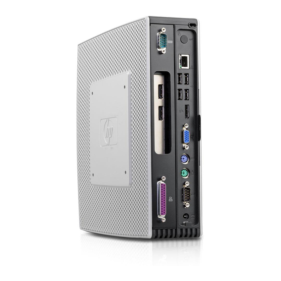
Page 10: Rear Panel Components
Rear Panel Components Figure 1-4 Rear panel components Wireless antenna* PS/2 connectors (2) Ethernet RJ-45 connector Serial connector Universal serial bus (USB) connectors (4) Power connector DisplayPort connector Power cord retention slot VGA connector *Available on some models. Refer to the model-specific QuickSpecs at www.hp.com for details. The wireless antenna allows you to send and receive wireless signals to communicate with wireless local area networks (WLAN). -
Page 11: Installing The Antenna (Wireless Models)
Installing the Antenna (Wireless Models) ▲ Screw the antenna in place on the rear of the thin client. Figure 1-5 Installing the antenna CAUTION: To prevent damage to the antenna mounting, do not overtighten the antenna. Installing the Rubber Feet To install the rubber feet: Lay the thin client on its right side. -
Page 12: Removing The Stand
To install the stand: Turn unit upside down. Locate the slots on the bottom of the unit into which the tabs on the stand fit. Insert the tabs into the slots (1), and then slide the stand about 1.26 cm (1/2 inch) toward the front of the unit until it locks into place (2). -
Page 13: Using The Power Cord Retention Slot
Using the Power Cord Retention Slot To prevent accidental disconnection, press a loop of the power cord into the power cord retention slot. Figure 1-9 Power cord retention slot Using the Keyboard Figure 1-10 Keyboard features Caps Lock Activates/deactivates the Caps Lock feature. Scroll Lock Activates/deactivates the Scroll Lock feature. - Page 14 Use in combination with another key; its function depends on the application software you are using. Similar to the right mouse button, opens pop-up menus in a Microsoft Application key Office application. May perform other functions in other software applications. Editing keys Includes the following: Insert, Home, Page Up, Delete, End,...
-
Page 15: Windows Logo Key
Windows Logo Key Use the Windows Logo Key in combination with other keys to perform certain functions available in Windows operating systems. Windows Logo Key + Switch between open items. Windows Logo Key + Open My Computer. Windows Logo Key + Search for a file or folder. -
Page 16: Serial Number Location
Serial Number Location Every thin client includes a unique serial number located as shown in the following illustration. Have this number available when contacting HP customer service for assistance. Figure 1-11 Serial number location Chapter 1 Product Features ENWW... -
Page 17: Hardware Changes
Hardware Changes General Hardware Installation Sequence To ensure the proper installation thin client hardware components: Back up any data, if necessary. If the thin client is powered on: Turn the unit and any other attached devices off. Disconnect the power cord from the wall outlet. Disconnect any external devices or cables, such as an antenna or cable lock. -
Page 18: Removing And Replacing The Secure Usb Compartment Cover
Install the stand, if you will be using the thin client unmounted in a vertical orientation. See Installing the Stand on page 5 for more information. Replace the secure USB compartment cover. See Removing and Replacing the Secure USB Compartment Cover on page 12 for more information. -
Page 19: Replacing The Secure Usb Compartment Cover
Remove the cover from the unit by first lifting the rear (screw side) of the cover, and then lifting the cover off the unit (3). Figure 2-1 Removing the secure USB compartment cover Replacing the Secure USB Compartment Cover To replace the secure compartment cover: Place the cover on top of the unit so it is offset about 1.27 cm (1/2 inch) toward the rear of the unit, allowing the tabs on the cover to align and insert into the slots on the chassis (1). -
Page 20: Removing And Replacing The Side Access Panel And Metal Side Cover
Removing and Replacing the Side Access Panel and Metal Side Cover Removing the Side Access Panel and Metal Side Cover WARNING! Before removing the side access panel, ensure that the thin client is turned off and the power cord is disconnected from the electrical outlet. To remove the access panel: Remove the secure USB compartment cover (1). -
Page 21: Replacing The Metal Side Cover And Side Access Panel
Lift the metal side cover, front side first, off the unit (2). Figure 2-4 Removing the metal side cover Replacing the Metal Side Cover and Side Access Panel To replace the metal side cover: Place the metal side cover on the chassis, rear edge first, making sure to insert the tabs in the rear edge of the cover in the holes in the chassis (1). -
Page 22: Installing Thin Client Options
Slide the panel toward the bottom of the unit until it locks into place (2). Figure 2-6 Replacing the side access panel Installing Thin Client Options Various options can be installed on the thin client: ● Installing the USB Device on page 17 ●... -
Page 23: Installing The Usb Device
Installing the USB Device Before beginning the replacement process, review General Hardware Installation Sequence on page 11 for procedures you should follow before and after installing or replacing hardware. ▲ Insert the USB device into the USB port in the secure USB compartment. See the following illustration for the location of the ports in the secure USB compartment. -
Page 24: Installing A Secondary Flash Memory Module
To release the battery from its holder, squeeze the metal clamp that extends above one edge of the battery. When the battery pops up, lift it out (1). Figure 2-8 Removing and replacing the internal battery To insert the new battery, slide one edge of the replacement battery under the holder’s lip with the positive side up. -
Page 25: Installing A Second So-Dimm
CAUTION: Static electricity can damage the electronic components of the computer or optional cards. Before beginning these procedures, ensure that you are discharged of static electricity by briefly touching a grounded metal object. When handling a memory module, be careful not to touch any of the contacts. - Page 26 To install the SO-DIMM: Slide the serial number tab out of the way. NOTE: Be sure not to lose this tab. Remove the access plate: Figure 2-10 Removing the SO-DIMM access plate Remove the two screws securing the access plate to the chassis. Lift the rear edge of the plate and pull the plate back and up off the chassis.
-
Page 27: Installing The Pci Express Expansion Module And Pci Express Card
Replace the access plate: Figure 2-12 Replacing the SO-DIMM access plate Insert the tab on the front edge into its slot and set the plate into position. NOTE: You may need to press lightly on the access plate to position it properly against the chassis. -
Page 28: Appendix A Specifications
Specifications Table A-1 HPt5740/t5745 Thin Client Dimensions 222 mm 8.74 in. Width (front to back) 255 mm 10.04 in Height (top to bottom, without stand) 44 mm 1.73 in. Depth (side to side) Approximate Weight 1.53 kg 3.37 lb Temperature Range (fanless design)* Operating** 10°... -
Page 29: Appendix B Security Provisions
Security Provisions Securing the Thin Client The HPt5740/t5745 thin client is designed to accept a security cable lock. This cable lock prevents unauthorized removal of the thin client, as well as locking the secure compartment. To order this option, visit the HP Web site at http://h30094.www3.hp.com/product.asp? sku=2563044&pagemode=ca. -
Page 30: Appendix C Mounting The Thin Client
Mounting the Thin Client HP Quick Release The HPt5740/t5745 thin client incorporates four mounting points on each side of the unit. These mounting points follow the VESA (Video Electronics Standards Association) standard, which provides industry-standard mounting interfaces for Flat Displays (FDs), such as flat panel monitors, flat displays, and flat TVs. - Page 31 To use the HP Quick Release with a VESA-configured thin client: Using four 15 mm screws included in the mounting device kit, attach one side of the HP Quick Release to the thin client as shown in the following illustration. Figure C-2 Connecting the HP Quick Release to the thin client Using four screws included in the mounting device kit, attach the other side of the HP Quick...
-
Page 32: Supported Mounting Options
Slide the side of the mounting device attached to the thin client (1) over the other side of the mounting device (2) on the device on which you want to mount the thin client. An audible 'click' indicates a secure connection. Figure C-4 Connecting the thin client NOTE:... - Page 33 Figure C-6 Thin client mounted on back of monitor stand ● You can mount the thin client on a wall. Figure C-7 Thin client mounted on wall ● You can mount the thin client under a desk. Figure C-8 Thin client mounted under desk HP Quick Release ENWW...
-
Page 34: Non-Supported Mounting Option
Non-supported Mounting Option CAUTION: Mounting a thin client in an non-supported manner could result in failure of the HP Quick Release and damage to the thin client and/or other equipment. Do not mount the thin client on a flat panel monitor stand, between the panel and the stand. Figure C-9 Unsupported mounting position—thin client between stand and monitor Appendix C Mounting the Thin Client... -
Page 35: Appendix D Thin Client Operation
Thin Client Operation Routine Thin Client Care Use the following information to properly care for your thin client: ● Never operate the thin client with the outside panel removed. ● Keep the thin client away from excessive moisture, direct sunlight, and extreme heat and cold. For information about the recommended temperature and humidity ranges for the thin client, see Specifications on page ●... - Page 36 Figure D-2 Horizontal orientation ● You can lay the thin client under a monitor stand with at least one inch of clearance. Figure D-3 Under monitor stand CAUTION: If a secondary flash memory module is installed, do not operate the thin client in a horizontal orientation or under a monitor stand.
-
Page 37: Non-Supported Orientation
Non-supported Orientation HP does not support the following orientation for the thin client. CAUTION: Non-supported placement of thin clients could result in operation failure and/or damage to the devices. CAUTION: Thin clients require proper ventilation to maintain operating temperature. Do not block the vents. -
Page 38: Appendix E Electrostatic Discharge
Electrostatic Discharge A discharge of static electricity from a finger or other conductor may damage system boards or other static-sensitive devices. This type of damage may reduce the life expectancy of the device. Preventing Electrostatic Damage To prevent electrostatic damage, observe the following precautions: ●... -
Page 39: Appendix F Shipping Information
Shipping Information Shipping Preparation Follow these suggestions when preparing to ship the thin client: Turn off the thin client and external devices. Disconnect the power cord from the electrical outlet, then from the thin client. Disconnect the system components and external devices from their power sources, then from the thin client. -
Page 40: Index
Index flash memory module, installing access panel line-out audio location 4 removing 14 front panel components 2 lock, cable, slot location 3 replacing 15 function keys 9 altitude specifications 22 management solutions 2 antenna grounding methods 32 memory module, installing 18 installing 5 metal side cover location 3... - Page 41 power supply 22 wireless antenna rated output current 22 rated output current 22 installing 5 rear panel components 4 relative humidity 22 location 3 relative humidity specifications temperature 22 thin client 22 removing weight 22 battery 17, 19 stand metal side cover 14 installing 5 secure USB compartment removing 6...
Need help?
Do you have a question about the t5740e - Thin Client and is the answer not in the manual?
Questions and answers