Table of Contents
Advertisement
Quick Links
Advertisement
Table of Contents

Related Manuals for NEC NP03WK


Summary of Contents for NEC NP03WK
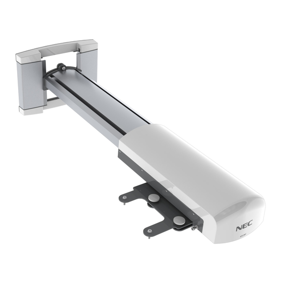
- Page 1 Wall Mount Unit NP02WK & NP03WK Installation and Adjustment Manual...
-
Page 2: Table Of Contents
Wall Mount Unit Installation and Adjustment Manual Thank you for your purchase of this NEC wall mount unit. Please read this installation and adjustment manual carefully to ensure proper use. The Wall Mount Unit NP02WK/NP03WK is exclusively for Projector NP-M260XS/M300XS/ M350XS/M260WS/M300W and cannot be used for other projectors. -
Page 3: Please Heed The Following
Please heed the following Symbol In this “Installation and Adjustment Manual”, to ensure the safe and proper use of the product, prevent harm to yourself and others and damage to property, various symbols are used. The symbols and meanings are as follows. Please read this manual after ensuring the contents are well understood. - Page 4 Warning • Do not install in places subject to constant vibration. Extended vibration may cause loosening of the screws and result in the Wall Mount Unit and projector falling and causing injury. Also, it may cause breakdown of the projector. •...
-
Page 5: Preparation
Preparation Packaged Parts Please check the packaged items. * The package shall either contains arm for NP02WK or NP03WK Cover (A, B):2 pairs Arm NP02WK:1 Wall adapter:1 Arm NP03WK:1 Arm cover:1 Plate (B):1 M4×20 screws:4 M3.5×9.4 screws:2 Projector adapter:1 Hex wrench:1 Optional Wall plate:1 *1 Installation and Adjustment... -
Page 6: Names Of Parts
Names of Parts Arm cover Elongate hole for screw (or bolt) (4 parts) Covers (A, B) Plate (A) • Arm fixation screw Grooves for wiring Tilt adjust knobs (4 parts) Wall adapter Cover (B, A) Central axis Projector adapter Plate (B) Horizontal fixation nut •... -
Page 7: Dimensions Of Parts
Dimensions of Parts: (unit: mm) The dimensions of the positions of the wall fixation screws (bolts) of the wall adapter are described Central axis The center of the wall adapter (central axis) 885 (minimum) -1245 (maximum) NP02WK 1160 (minimum) -1520 (maximum) NP03WK 1125 Projector bottom surface... -
Page 8: Mounting The Projector
Mounting the Projector Preparations 1. Determine the installation location of the screen, and accordingly decide the installation position of the wall mount unit. Refer to the section "Installation" in the user’s manual included with the projector for more information. • Installation for slanted projection is not possible. Determine the position for frontprojection. 2. - Page 9 l l a . r e Thread the cables through the arm plates and the arm. NP02WK: Loosen the arm fixation screws (top and bottom) with the supplied hex wrench. NP03WK: Loosen the arm fixation screws (2 on top and 2 on bottom) with the supplied hex wrench. Insert the arm plate (A) into the wall adapter from the top and tighten the screws (top and bottom) near the center of the elongated hole.
- Page 10 Use the two supplied M5.5x9.5 screws to securely attach the supplied plate (B) to the arm. Plate (B) Warning If plate (B) is not installed, the projector may slide out of the arm and fall off, wh ich may cause injury.
-
Page 11: Adjusting The Projection Position
Adjusting the Projection Position Preparations Before adjusting Project an image from the projector, then first use the focus lever of the projector to roughly adjust the focus of the projected image. For information on how to project an image, see “Installation and Connections” and“ Projecting an Image (Basic Operation)”... - Page 12 Turn the left or right knob to adjust projector tilt in the left or right direction. - When the knob shown in black in the illustration is ti g hte ned, the projector is rotated in the counterclockwise direction. When the adjustment is complete, tighten the opposite knob that is still loosened.
- Page 13 4. Adjust the tilt. Tilt adjustment is performed with the four adjustment knobs. Front/rear tilt adjustment Adjust together Rotation axis Left/right tilt adjustment Fine adjustment in same direction as for vertical adjustment Adjust together Rotation axis • If tilt adjustment achieved with these knobs is not suf cient, repeat the adjustment process from step 2 on page E-12.
-
Page 14: Specifications
t t A c e j r o t r e t l l a . r e t l l a Slide the two coverstowards the center while pushing them down, as shown in the illustration. The bottom of each cover will then engage with the screw heads of the wall adapter.
Need help?
Do you have a question about the NP03WK and is the answer not in the manual?
Questions and answers