Table of Contents
Advertisement
Quick Links
UV and Solar Radiation Sensors
®
For Vantage Pro
and Vantage Pro2
The Davis Instruments UV Sensor is a precision instru-
ment that detects ultraviolet (UV) radiation at wave-
lengths of 290 to 390 nanometers. The spectral
response is closely matched to the Erythema Action
Spectrum, defined by McKinlay and Diffey (1987) and
internationally recognized as the radiation that is most
responsible for causing redness of the human skin.
The Davis Instruments Solar Radiation Sensor is a pre-
cision instrument that detects radiation at wavelengths
of 300 to 1100 nanometers. The spectral response of
the silicon photodiode detector is a good match to the
spectrum of solar irradiance.
Typically, users install both the Solar Radiation Sensor and the Davis UV Sensor. How-
ever, users may install only one of these sensors. Unless otherwise noted, instructions
in this manual apply to both sensors.
Individual specifications for each sensor are listed on the Davis Website at
http://www.davisnet.com/support/weather/ under the spec sheets link.
Note:
Sunburn is not the only consequence of exposure to UV radiation. Skin cancers, cataracts, and dam-
age to the immune system are caused by UV radiation. Exposure to UV radiation should be mini-
mized.
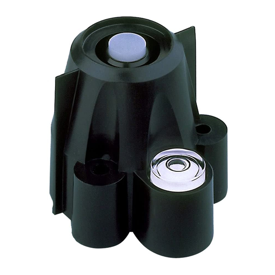
The UV Sensor is comprised of the following components:
Shield—The outer shell shields the sensor body from thermal radiation and provides a
path for convection cooling of the body, minimizing heating of the sensor interior. It
provides a cutoff ring for cosine response, a level indicator, and fins to aid in aligning
the sensor with the sun's rays.
Sensor Body—Houses the following components:
• Diffuser—Provides, with gasket, a weather-tight seal and excellent cosine response.
• Filter—Provides the Erythema Action spectral response. Encased in multiple hard-
oxide coatings, the filter is stable in the presence of heat and humidity.
• Detector—Contains a semiconductor diode that, with the filter, responds to radia-
tion only in the specified wavelengths.
• Amplifier—Converts the detector current into a 0 to +2.5V signal.
The Solar Radiation Sensor is comprised of the following components:
Shield —Serves the same role as in the UV Sensor.
Sensor Body —Composed of a shield, the same as that in the UV Sensor; and a sensor
body, which contains a precision machined diffuser giving excellent cosine response; a
hermetically sealed silicon photodiode; and an amplifier.
™
Weather Stations
Products #6450 and #6490
Advertisement
Table of Contents

Related Manuals for DAVIS Solar and UV Radiation Sensors


Summary of Contents for DAVIS Solar and UV Radiation Sensors
- Page 1 Typically, users install both the Solar Radiation Sensor and the Davis UV Sensor. How- ever, users may install only one of these sensors. Unless otherwise noted, instructions in this manual apply to both sensors.
- Page 2 Sensor Interface Module (SIM) Box. Before permanently install- ing your new sensor, Davis Instruments recommends that you test it first. To do this, take your console with you out to your ISS, and follow the instructions below.
- Page 3 If you still see no reading, reconnect the sensor cable to the ISS, ensuring it is in the proper receptacle. If you still see no reading, contact Davis Technical Support (see Techni- cal Support at the back of this manual).
- Page 4 Due to the sensitivity of ultraviolet and solar radiation sensors, it is common practice for manufacturers to recommend recalibration after a period of time. Here at Davis Instruments, we have seen approximately 2% drift per year on the readings from these sensors.
Need help?
Do you have a question about the Solar and UV Radiation Sensors and is the answer not in the manual?
Questions and answers