
Related Manuals for 3Com 4200G PWR


Summary of Contents for 3Com 4200G PWR
- Page 1 ® 3Com Switch 4200G Family Getting Started Guide 4200G 12-Port (3CR17660-91) 4200G 24-Port (3CR17661-91) 4200G 48-Port (3CR17662-91) www.3Com.com Part No. 10014914 Rev. AA Published July 2006...
- Page 2 All other company and product names may be trademarks of the respective companies with which they are associated. ENVIRONMENTAL STATEMENT It is the policy of 3Com Corporation to be environmentally friendly in all operations. To uphold our policy, we are committed to: Establishing environmental performance standards that comply with national legislation and regulations.
- Page 3 SOFTWARE AND DOCUMENTATION FOR YOUR OM SWITCH Thank you for purchasing a 3Com Switch 4200G Family switch. As part of our commitment to bringing you the most capable and dependable network equipment, 3Com offers free software maintenance updates and documentation updates on our website.
-
Page 5: Table Of Contents
ONTENTS OWNLOAD THE LATEST SOFTWARE AND DOCUMENTATION FOR YOUR OM SWITCH BOUT UIDE Before You Start Release Notes About Your CD-ROM Conventions Related Documentation Accessing Online Documentation Documentation Comments 4200G F NTRODUCING THE WITCH AMILY About the Switch 4200G Summary of Hardware Features Switch 4200G—Front View Detail 10/100/1000BASE-T Ports 1000BASE-X SFP Ports... - Page 6 Manually Configuring IP Information Connecting to the Console Port Connecting to a Front Panel Port Viewing Automatically Configured IP Information Using 3Com Network Director Connecting to the Console Port Setting Up Command Line Interface Management User Interface Overview CLI Management using the Console Port...
- Page 7 ONTENTS Prerequisites Web Management Over the Network Setting Up SNMP Management V1 or V2 Prerequisites Default Users and Passwords Configuration Conversion Utility ROBLEM OLVING Solving Problems Indicated by LEDs Solving Hardware Problems Solving Communication Problems PGRADING OFTWARE Upgrade methods Upgrading from the Command Line Interface Check Flash Space Available Backup Switch Software Upgrade Using TFTP...
- Page 8 ONTENTS AFETY NFORMATION Power Cord Set—Japan Important Safety Information L’information de Sécurité Importante Wichtige Sicherheitsinformationen Información de Seguridad Importante Importanti Informazioni di Sicurezza Ważne informacje o zabezpieczeniach OUTS Null Modem Cable PC-AT Serial Cable Modem Cable Ethernet Port RJ-45 Pin Assignments ECHNICAL PECIFICATIONS Switch 4200G 12-Port...
-
Page 9: About This Guide
A link to 3Com Network Director software. ■ A number of other useful links. ■ Most user guides and Release Notes are available in Adobe Acrobat Reader Portable Document Format (PDF) or HTML on the 3Com World Wide Web site: http://www.3com.com/... -
Page 10: Conventions
BOUT UIDE Conventions Table 1 and Table 2 list conventions that are used throughout this guide. Table 1 Notice Icons Icon Notice Type Description Information note Information that describes important features or instructions Caution Information that alerts you to potential loss of data or potential damage to an application, system, or device Warning Information that alerts you to potential personal injury... -
Page 11: Related Documentation
Related Documentation Related In addition to this guide, Switch 4200G documentation set includes the Documentation following: Switch 4200G Configuration Guide ■ This guide contains information on the features supported by your Switch and how they can be used to optimize your network. It is supplied in PDF format on the CD-ROM that accompanies the Switch. -
Page 12: Documentation Comments
Switch 4200G Family Getting Started Guide Page 21 Please note that we can only respond to comments and questions about 3Com product documentation at this e-mail address. Questions related to technical support or sales should be directed in the first instance to your network supplier. -
Page 13: Introducing The Switch 4200G Family
NTRODUCING THE 4200G F WITCH AMILY This chapter contains introductory information about the Switch 4200G and how it can be used in your network. It covers summaries of hardware and software features and also the following topics: About the Switch 4200G ■... -
Page 14: About The Switch 4200G
1: I 4200G F HAPTER NTRODUCING THE WITCH AMILY About the Switch The Switch 4200G Family are mixed media devices which consist of: 4200G 12, 24 or 48 10/100/1000BASE-T ports ■ Four 1000BASE-X SFP ports ■ One option module slot for a 10 Gigabit Ethernet port module on the ■... -
Page 15: Switch 4200G-Front View Detail
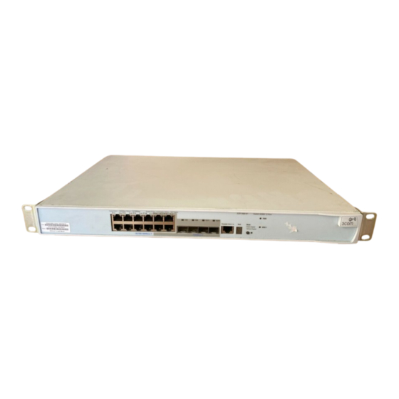
Switch 4200G—Front View Detail Table 3 Hardware Features (continued) Feature Switch 4200G Mounting 19-inch rack or standalone mounting Clustering Up to 16 units can be linked together (15 members and 1 commander) Switch 4200G—Front View Figure 1 Switch 4200G 12-Port—front view Detail Unit Status Display... -
Page 16: 10/100/1000Base-T Ports
1: I 4200G F HAPTER NTRODUCING THE WITCH AMILY Figure 3 Switch 4200G 48-Port—front view Unit Status Display Mode Switch Console Port Power Mode Port Status LEDs Mode Power:Green = Deliverng Power. Yellow=Fault, Flashing Green=Over Budget Speed:Green = 100Mbps, Yellow = 10Mbps Duplex:Green = Full Duplex, Yellow = Half Duplex Green=Speed Yellow=Duplex... -
Page 17: 1000Base-X Sfp Ports
Switch 4200G—Front View Detail 1000BASE-X SFP Ports SFP (Small Form Factor Pluggable) ports support fiber Gigabit Ethernet long-wave (LX), long-haul (LH70) and copper (T) SFP Transceivers in any combination. This offers you the flexibility of using SFP transceivers to provide connectivity between the Switch and remote 1000 Mbps workgroups or to create a high capacity aggregated link backbone connection. -
Page 18: Leds
1: I 4200G F HAPTER NTRODUCING THE WITCH AMILY Table 4 Status Display (continued) Display Mode LED Color Description Rotating bar segment Mode LED flashing green Software download in progress. Flashing “F” Mode LED steady red Fan failure detected. Flashing “t” Mode LED flashing red Switch is too hot;... -
Page 19: Switch 4200G - Rear View Detail
Switch 4200G — Rear View Detail Table 5 LED Behavior (continued) Color Indicates Duplex Green Full duplex, blinking off for every packet received or transmitted. Yellow Half duplex, blinking off for every packet received or transmitted. Yellow flashing The port has failed POST. No link is present. -
Page 20: Default Settings
1: I 4200G F HAPTER NTRODUCING THE WITCH AMILY Default Settings Table 6 shows the default settings for the Switch 4200G Family. Table 6 Default Settings Feature Switch 4200G Automatic IP Configuration Enabled Port Status Enabled Port Speed Auto-negotiated Duplex Mode Auto-negotiated Flow Control Auto-negotiated... -
Page 21: Installing The Switch
NSTALLING THE WITCH This chapter contains the information you need to install and set up the Switch 4200G. It covers the following topics: Package Contents ■ Choosing a Suitable Site ■ Rack-mounting ■ Placing Units On Top of Each Other ■... -
Page 22: Package Contents
2: I HAPTER NSTALLING THE WITCH AVVERTENZA: Informazioni di sicurezza. Prima di installare o rimuovere qualsiasi componente dal Switch 4200G o di eseguire qualsiasi procedura di manutenzione, leggere le informazioni di sicurezza riportate nell'Appendice A della presente guida per l'utente. OSTRZEŻENIE: Informacje o zabezpieczeniach. -
Page 23: Rack-Mounting
■ Air flow is not restricted around the Switch or through the vents in the ■ side of the Switch. 3Com recommends that you provide a minimum of 25mm (1in.) clearance. Air temperature around the Switch does not exceed 40 (104 °C... - Page 24 3Com product name of the Switch ■ 3Com 3C number of the Switch ■ Unique MAC address (Ethernet address) of the Switch ■ Serial number of the Switch ■ You may need this information if you contact 3Com Technical Support.
-
Page 25: Placing Units On Top Of Each Other
If the Switch units are free-standing, up to four units can be placed one Top of Each Other on top of the other. If you are mixing a variety of 3Com equipment, the smaller units must be positioned at the top. -
Page 26: Sfp Operation
■ 3CSFP93 SFP (1000BASE-T) ■ To access the latest list of approved SFP transceivers for the Switch on the 3Com Corporation World Wide Web site, enter this URL into your internet browser: http://www.3com.com Inserting an SFP To be recognized as valid, the SFP transceiver must have the following... - Page 27 If the SFP transceiver is faulty, it will not operate within the Switch. See “Solving Hardware Problems” on page 55. 3Com recommends that you only use SFPs supplied by 3Com. If the SFP transceiver is invalid it will not be recognized by the Switch.
-
Page 28: Removing An Sfp Transceiver
MDI port, you need to use a standard straight-through cable. See Table 8. 3Com recommends that you use at least Category 5 twisted pair cable—the maximum segment length for this type of cable is 100 m (328 ft.). -
Page 29: Choosing The Correct Cables For The Switch 4200G
Choosing the Correct Cables CAUTION: If you want to install the Switch using a Category 5E or Category 6 cable, 3Com recommends that you briefly connect the cable to a grounded port before connecting network equipment. If you do not, the cable’s Electrostatic Discharge (ESD) may damage the Switch's port. - Page 30 2: I HAPTER NSTALLING THE WITCH...
-
Page 31: Setting U P For Management
ETTING P FOR ANAGEMENT To make full use of the features offered by your Switch, and to change and monitor the way it works, you have to access the management software that resides on the Switch. This is known as managing the Switch. -
Page 32: Methods Of Managing A Switch
3: S HAPTER ETTING P FOR ANAGEMENT Methods of To manage your Switch you can use one of the following methods: Managing a Switch Command line interface management ■ Command line interface management using SSH ■ Web interface management ■ SNMP management ■... -
Page 33: Command Line Interface Management Using Ssh
Refer to “Setting Up Web Interface Management” on page 48. SNMP Management You can manage a Switch using any network management workstation running the Simple Network Management Protocol (SNMP) as shown in Figure 10. For example, you can use the 3Com Network Director software, available from the 3Com website. -
Page 34: Setting Up Overview
3: S HAPTER ETTING P FOR ANAGEMENT Figure 10 SNMP Management over the Network SNMP Network Management Switch Workstation Connect over Network using SNMP Refer to “Setting Up SNMP Management V1 or V2” on page 50. Setting Up This section gives an overview of what you need to do to get your Switch Overview set up and ready for management when it is in its default state. -
Page 35: Setting Up Overview
How do you want to connect to the Switch? configured IP information? Connect to the con- Connect to a front panel port Use 3Com Network Connect to the console and use the Web Interface or sole port and use the Director (3ND). -
Page 36: Ip Configuration
(Static IP addresses are necessary to ensure that the Switch is always allocated the same IP information.) For most installations, 3Com recommends that you configure the Switch IP information manually. This makes management simpler and more reliable as it is not dependent on a DHCP or BootP server, and eliminates the risk of the IP address changing. -
Page 37: Preparing For Management
“Switch 4200G Command Reference Guide” on the CD-ROM that is supplied with the Switch or on the 3Com Web site. Manually You can manually configure the Switch IP information in the following... -
Page 38: Connecting To The Console Port
3: S HAPTER ETTING P FOR ANAGEMENT Connecting to the To set up your Switch manually you can make a connection to the console Console Port port, (this example describes a local connection to the console port, rather than one using a modem). You can do this whilst the Switch is offline, that is, before you connect the Switch to a network, or whilst the Switch is online, that is, connected to a network. -
Page 39: Setting Up Switch With Ip Information
Manually Configuring IP Information 2 Open your terminal emulation software and configure the COM port settings to which you have connected the cable. The settings must be set to match the default settings for the Switch, which are: 19,200 baud (bits per second) ■... - Page 40 3: S HAPTER ETTING P FOR ANAGEMENT Figure 13 User View Login 3 Enter the system-view command and Enter. To confirm that you are in the System View, the following should be displayed: [S4200G] Enter interface vlan 1 and Enter. 4 Enter the IP address and subnet mask for the Switch as follows: ip address xxx.xxx.xxx.xxx mmm.mmm.mmm.mmm and Enter.
-
Page 41: Connecting To A Front Panel Port
Manually Configuring IP Information Connecting to a Front To set up your Switch manually you can, alternatively, make a connection Panel Port to a front panel port. To do this you will need an IP address, refer to “Viewing Automatically Configured IP Information” on page 44 for more information. - Page 42 3: S HAPTER ETTING P FOR ANAGEMENT To connect the cable: a Attach an RJ-45 connector at one end of the Ethernet cable to the Network Interface Card (NIC) in the workstation. b Connect the RJ-45 connector at the other end of the cable to one of the front panel ports on the Switch.
- Page 43 Manually Configuring IP Information Using Command Line Interface using Telnet 1 To start a Telnet session to the unit, click Start in Microsoft Windows 95/98/2000/NT/XP. a Click Run. b In the dialogue box that appears type the IP address of the unit, that is: Telnet xxx.xxx.xxx.xxx (where xxx.xxx.xxx.xxx is the IP address of the Switch) c Click OK.
-
Page 44: Viewing Automatically Configured Ip Information
IP address the Switch will be given. Refer to the documentation that accompanies your DHCP or BootP server. If your network does not have a DHCP or BootP server, the workstation running 3Com Network Director must be on the same subnet as the Switch, because Auto-IP addresses are non-routable. -
Page 45: Connecting To The Console Port
Viewing Automatically Configured IP Information Connecting to the Alternatively, you can view the automatically configured IP information Console Port using the command line interface (CLI) through a connection to the console port. (This example describes a local connection to the console port, rather than a remote one using a modem.) For further information on connecting using the console port see “Connecting the Workstation to the Switch”on page 38. -
Page 46: Setting Up Command Line Interface Management
3: S HAPTER ETTING P FOR ANAGEMENT 4 Enter display ip interface br to view a summary of allocated IP addresses. The initial set up of your Switch is now complete and the Switch is ready for you to set up your chosen management method. See “Methods of Managing a Switch”... -
Page 47: Setting Up Command Line Interface Management Using Ssh
Setting Up Command Line Interface Management using SSH 3 Check you can communicate with the Switch by entering a ping command at the DOS prompt in the following format: c:\ ping xxx.xxx.xxx.xxx (where xxx.xxx.xxx.xxx is the IP address of the Switch) If you get an error message, check that your IP information has been entered correctly and the Switch is powered up. -
Page 48: Setting Up Web Interface Management
4 Install an SSH client application on the workstation you want to use to access the switch. 3Com recommends the following SSH clients; PuTTY, OpenSSH and SSH Communications Security Corp Secure Shell. 5 Open an SSH session and access the Switch using the Switch’s IP address and port number. -
Page 49: Web Management Over The Network
Setting Up Web Interface Management Table 9 Supported Web Browsers and Platforms Windows Windows Red Hat Solaris 2000 Windows XP Server 2003 Linux 9 ✓ ✓ ✕ ✕ ✓ Netscape 7.1 ✓ ✓ ✓ ✕ ✕ Internet Explorer 5.5 ✓ ✓... -
Page 50: Setting Up Snmp Management V1 Or V2
VLAN 1 (the Default VLAN). By default, all ports on the Switch are in VLAN 1. You can use the 3Com Network Director application that is available from the 3Com website to provide SNMP management for your Switch. If you use 3Com Network Director it automatically loads the correct MIBs and necessary files onto your workstation. -
Page 51: Configuration Conversion Utility
The 3Com Switch 4200G Configuration Conversion Utility (CCU) enables Conversion Utility you to convert the key configuration parameters from a range of 3Com SuperStack II and SuperStack 3 devices to the configuration file format used by your Switch 4200G unit. The utility provides conversion for a... - Page 52 3: S HAPTER ETTING P FOR ANAGEMENT To download the CCU package, select the CCU link on the CD that accompanies your Switch 4200G. Alternatively, the CCU download and further information is available at: http://www.3com.com/switchmigration/...
-
Page 53: Problem Solving
ROBLEM OLVING This chapter helps you to diagnose and solve problems you may have with the operation of your Switch. There is also an explanation of IP addressing and upgrading software. The topics covered are: Solving Problems Indicated by LEDs ■... -
Page 54: Solving Problems Indicated By Leds
4: P HAPTER ROBLEM OLVING Solving Problems If the LEDs on the Switch indicate a problem, refer to the list of suggested Indicated by LEDs solutions below. The PWR LED does not light Check that the power cable is firmly connected to the Switch and to the supply outlet. -
Page 55: Solving Hardware Problems
Solving Hardware Problems Auto-negotiation problems will occur with 10BASE-T or 100BASE-T where auto-negotiation is disabled and incorrect cables are being used (cross-over or straight) Auto-negotiation problems will occur with fiber if: The Receiver (RX) and Transceiver (TX) cable connectors are ■... - Page 56 3 Power cycle the unit. To do this, remove and reconnect the AC mains supply. If another fan failure warning message is generated using the Command Line Interface or the Web interface, return the unit to 3Com. Unit fails, no SNMP fan failure message is received 1 Power cycle the unit.
-
Page 57: Solving Communication Problems
IP address of the router. The Switch’s IP address has been entered correctly in your network ■ management application (such as 3Com Network Director). The following is a brief overview of IP addressing, and how to obtain a registered IP address. - Page 58 If your IP network is internal to your organization only, that is, you do not access the Internet, you may use any arbitrary IP address as long as it is not being used by another device on your network. 3Com suggests you use addresses in the range 192.168.0.0 to 192.168.255.255 with a subnet mask of 255.255.255.0.
-
Page 59: Upgrading Software
Note: If you need a TFTP or FTP server, we offer TFTP/FTP servers on www.3Com.com. Search for “tftp server”. The applications are located on the link to “3Com Software Library - Utilities for 32 bit Windows”. These applications run on Windows platforms. -
Page 60: Upgrading From The Command Line Interface
5: U HAPTER PGRADING OFTWARE Upgrading from the This section describes how to upgrade files to your Switch from the Command Line Command Line Interface (CLI). Interface The basic procedure is to check that you have enough space available in flash memory, backup your existing Switch software, and then upgrade the Switch software. -
Page 61: Backup Switch Software
Upgrading from the Command Line Interface 3 The /unreserved option will cause the file to be deleted from both the flash and the recycle-bin. To check that deleted files have been removed from the recycle-bin enter the following: <4200G> reset recycle-bin unit1>flash:/ If the recycle-bin is empty the following is displayed: % Recycle bin in this directory is empty Backup Switch... - Page 62 5: U HAPTER PGRADING OFTWARE Table 11 Switch 4200G Filenames Filename Prefix/Suffix Switch s3t / .app Switch 4200G software s3u / .btm Switch 4200G bootrom software s3v / .web Switch 4200G web management software 2 To download the Web user interface file, enter: [4200G] tftp aaa.aaa.aaa.aaa get http.web 3 To download the default configuration file, enter: [4200G] tftp aaa.aaa.aaa.aaa get 3ComOScfg.def...
-
Page 63: Upgrade Using Ftp (Via Network Port)
Upgrading from the Command Line Interface After the update is complete and you have verified that everything is working, the files that were saved in the backup phase can be deleted from the file system. Upgrade Using FTP To upgrade your Switch’s software using FTP do the following: (via network port) 1 Backup the existing switch software files. - Page 64 5: U HAPTER PGRADING OFTWARE The following information is displayed if the download has been successful: 200 PORT command successful. 150 Opening ASCII mode data connection for vrpcfg.def(10986 bytes)..226 Transfer complete. FTP: 10986 byte(s) received in 8.046 second(s) 1000.00 byte(s)/sec. 7 To download the bootrom file, enter: [ftp] get s3u01_00.btm 8 To download the web management file, enter:...
-
Page 65: Xmodem (Using The Console Cable)
Upgrading from the Command Line Interface XModem (using the To upgrade software to your Switch using XModem do the following: console cable) 1 From the User View, enter: xmodem get unit1>flash:/3ComOScfg.def The following information is displayed: **** WARNING **** xmodem is a slow transfer protocol limited to the current speed settings of the auxiliary ports. -
Page 66: Upgrading From The Bootrom Interface
5: U HAPTER PGRADING OFTWARE Upgrading from the This section describes how to upgrade your Switch from the Bootrom Bootrom Interface Interface. Introduction When the Switch is running the initial boot phase using the console, the following prompt is displayed with a five second countdown timer: Press CTRL-B to enter Boot Menu... - Page 67 Upgrading from the Bootrom Interface 3 Select option 3 from the Boot Menu. A file list similar to the following is displayed: Boot menu choice: 3 File Number File Size(bytes) File Name ==================================================== snmpboots private-data.txt 3(*) 4649088 s3t03_01_00s56.app 576218 s3t03_01_03_0024.zip 10301 3comoscfg.def 10369...
-
Page 68: Tftp
5: U HAPTER PGRADING OFTWARE TFTP To upgrade software to your Switch using TFTP, do the following: 1 From the Boot Menu, select option 1 (Download application file to flash) to display the following: 1. Set TFTP protocol parameter 2. Set FTP protocol parameter 3. -
Page 69: Xmodem
Upgrading from the Bootrom Interface 2 Select option 2 to display the following: Load File name: Switch IP address: Server IP address: FTP User Name: FTP User Password: 3 Enter the file name, Switch IP address, Server IP address and FTP user name and password to display the following: Are you sure to download file to flash? Yes or No(Y/N) 4 Enter y and the following information is displayed to indicate the file is... -
Page 70: Upgrading The Bootrom
5: U HAPTER PGRADING OFTWARE 4 Press Enter to start the download. The following information is displayed: Now please start transfer file with XMODEM protocol If you want to exit, Press <Ctrl+X> Loading...CCCCCCCCCCCCCCCCCCCCCCCCCCCCC 5 As the file is downloading, start the XModem send file process with terminal emulation software, such as Microsoft Hyperterminal. -
Page 71: Bootrom Upgrade Using Tftp
Upgrading the Bootrom A similar screen will be displayed for the configuration files and the web files. In each case, the file is given the attribute “main” or “backup” Bootrom Upgrade To upgrade the bootrom firmware from the Boot menu using TFTP do the using TFTP following: 1 From the Boot menu, select option 6 to display the bootrom upgrade... -
Page 72: Bootrom Upgrade Using Xmodem
5: U HAPTER PGRADING OFTWARE 2 Select option 2 to display the following: Load File name: Switch IP address: Server IP address: FTP User Name: FTP User Password: 3 Enter the file name, Switch IP address, Server IP address, FTP user name and password to display the following: Are you sure to update your bootrom? Yes or No(Y/N) 4 Enter y and the following information is displayed to indicate the file is... - Page 73 Upgrading the Bootrom 4 Press Enter to start the download. The following information is displayed: Now please start transfer file with XMODEM protocol If you want to exit, Press <Ctrl+X> Loading ...CCCCCCCCCCCCCCCCCCCCCCCCCCCCC 5 As the file is downloading, start the XModem send file process with terminal emulation software, such as Microsoft Hyperterminal.
- Page 74 5: U HAPTER PGRADING OFTWARE...
-
Page 75: Safety Information
AFETY NFORMATION You must read the following safety information before carrying out any installation or removal of components, or any maintenance procedures on the Switch 4200G. WARNING: Warnings contain directions that you must follow for your personal safety. Follow all directions carefully. You must read the following safety information carefully before you install or remove the unit. -
Page 76: Power Cord Set-Japan
A: S PPENDIX AFETY NFORMATION urządzenia należy uważnie przeczytać poniższe informacje o bezpieczeństwie. Power Cord Set—Japan Important Safety Information WARNING: Installation and removal of the unit must be carried out by qualified personnel only. WARNING: If installing the Switch 4200G together (one on top of the other) with SuperStack II or SuperStack 3 units that are shallower than the 4200G, the Switch 4200G unit must be installed below the shallower units. - Page 77 Important Safety Information Europe only: The supply plug must comply with CEE 7/7 (“SCHUKO”). ■ The mains cord must be <HAR> or <BASEC> marked and ■ be of type H03VVF3GO.75 (minimum). Denmark The supply plug must comply with section 107-2-D1, ■...
-
Page 78: L'information De Sécurité Importante
A: S PPENDIX AFETY NFORMATION WARNING: Fiber Optic ports—Optical Safety Class 1 LASER PRODUCT Never look at the transmit laser while it is powered on. Never look directly at the fiber TX port and fiber cable ends when they are powered on. L’information de Sécurité... - Page 79 L’information de Sécurité Importante Danemark La prise mâle d'alimentation doit respecter la section 107-2 ■ D1 de la norme DK2 1a ou DK2 5a Europe La prise secteur doit être conforme aux normes CEE 7/7 ■ (“SCHKO”) LE cordon secteur doit porter la mention <HAR> ou ■...
- Page 80 A: S PPENDIX AFETY NFORMATION AVERTISSEMENT: Ports pour fibres optiques—sécurité sur le plan optique. Dispositif Laser de Classe 1 Ne regardez jamais le laser d'émission en utilisant un dispositif d'agrandissement, tant qu'il est sous tension. Ne regardez jamais directement le port TX à fibres optiques et les extrémités des câbles à fibres optiques tant qu'ils sont sous tension.
-
Page 81: Wichtige Sicherheitsinformationen
Wichtige Sicherheitsinformationen Wichtige Sicherheitsinformationen VORSICHT: Alle Verfahren die in dieser Anleitung beschrieben werden gelten für alle Modelle, sofern nicht anders angegeben. Wo eine Vorgehensweise für die Schalter 5500-SI 24 und Schalter 5500-SI 52 gilt wird nur der Begriff Schalter verwendet. Diese Anleitung ist für Netzwerkadministratoren vorgesehen, die für die Installation und das Einstellen von Netzwerkkomponenten verantwortlich sind;... -
Page 82: Información De Seguridad Importante
A: S PPENDIX AFETY NFORMATION Bedingungen sind nur gegeben, wenn auch die an das Gerät angeschlossenen Geräte unter SELV-Bedingungen betrieben werden. VORSICHT: RJ-45-Porte. Diese Porte sind geschützte Datensteckdosen. Sie dürfen weder wie normale traditionelle Telefonsteckdosen noch für die Verbindung der Einheit mit einem traditionellem privatem oder öffentlichem Telefonnetzwerk gebraucht werden. - Page 83 Información de Seguridad Importante ADVERTENCIA: Conjunto de cables eléctricos: Debe estar homologado para el país donde se utilice: EE.UU. y El conjunto de cables debe estar homologado por UL y ■ Canadá tener la certificación CSA. La especificación mínima del cable flexible es: Nº 18 AWG ■...
-
Page 84: Importanti Informazioni Di Sicurezza
A: S PPENDIX AFETY NFORMATION secundario etiquetado como neutro conectado directamente a tierra. †Impédance à la terre. ADVERTENCIA: Sólo para el Reino Unido: si conecta un módem al puerto de consola del 4200G, utilice sólo un módem que sea adecuado para la conexión con el sistema de telecomunicaciones. - Page 85 Importanti Informazioni di Sicurezza AVVERTENZA: Set dei cavi di alimentazione Deve essere approvato per il paese in cui viene utilizzato. Stati Uniti e Il cavo deve avere l'approvazione UL e la certificazione CSA ■ Canada La specifica minima per il cavo flessibile è: N. 18 AWG Tipo ■...
-
Page 86: Ważne Informacje O Zabezpieczeniach
A: S PPENDIX AFETY NFORMATION contrassegnato come Neutro, collegato direttamente a terra. †Impédance à la terre. AVVERTENZA: Solo Regno Unito. Se si collega un modem alla porta Console dello 4200G, utilizzare solo un modem idoneo per il collegamento con il sistema di telecomunicazioni. AVVERTENZA: Le porte RJ-45 sono prese dati RJ-45 schermate. - Page 87 Ważne informacje o zabezpieczeniach Niezbędna jest zgodność z przepisami kraju, w którym jest stosowany: Stany Zestaw przewodów musi posiadać zezwolenie UL oraz ■ Zjednoczone i certyfikat CSA. Kanada Minimalna specyfikacja przewodu giętkiego: Przewód typu ■ SV lub SJ 3 o średnicy 18 wg specyfikacji AWG. Zestaw przewodów musi posiadać...
- Page 88 A: S PPENDIX AFETY NFORMATION mente a tierra. †Impédance ŕ la terre. OSTRZEŻENIE: Tylko Wielka Brytania: Podczas podłączania modemu do portu konsoli Switch 4200G należy stosować tylko modem odpowiedni do podłączenia do sieci telekomuni- kacyjnej. OSTRZEŻENIE: Porty RJ-45. Są to ekranowane gniazda danych RJ-45. Nie mogą...
-
Page 89: Pin - Outs
OUTS Null Modem Cable RJ-45 to RS-232 25-pin 3Com Switch PC/Terminal Cable connector: RJ-45 female Cable connector: 25-pin male/female only required if screen Screen Shell Screen always required Ground Ground required for handshake PC-AT Serial Cable RJ-45 to 9-pin 3Com Switch... -
Page 90: Modem Cable
B: P PPENDIX OUTS Modem Cable RJ-45 to RS-232 25-pin 3Com Switch RS-232 Modem Port Cable connector: RJ-45 female Cable connector: 25-pin male Screen Screen Shell RT S Ground Ground Ethernet Port RJ-45 10/100 and 1000BASE-T RJ-45 connections. Pin Assignments... - Page 91 Ethernet Port RJ-45 Pin Assignments Pin Number 10/100 1000 Transmit Data + Bidirectional Data A+ Not assigned Bidirectional Data A- Not assigned Bidirectional Data D+ Transmit Data – Bidirectional Data D- Not assigned Bidirectional Data C+ Not assigned Bidirectional Data C-...
- Page 92 B: P PPENDIX OUTS...
-
Page 93: Specifications
–10 ° to +70 °C (14 ° to 158 °F) Operating Humidity 95% non-condensing Standards EN60068 to 3Com schedule (Package testing: paras 2.1, 2.2, 2.30, and 2.32. Operational testing: paras 2.1, 2.2, 2.30 and 2.13). Safety Agency Certifications UL 60950-1, EN 60950-1, CSA 22.2 No. 60950-1, IEC 60950-1. -
Page 94: Switch 4200G 24-Port
–10 ° to +70 °C (14 ° to 158 °F) Operating Humidity 95% non-condensing Standards EN60068 to 3Com schedule (Package testing: paras 2.1, 2.2, 2.30, and 2.32. Operational testing: paras 2.1, 2.2, 2.30 and 2.13). Safety Agency Certifications UL 60950-1, EN 60950-1, CSA 22.2 No. 60950-1, IEC 60950-1. -
Page 95: Switch 4200G (48-Port)
–10 ° to +70 °C (14 ° to 158 °F) Operating Humidity 95% non-condensing Standards EN60068 to 3Com schedule (Package testing: paras 2.1, 2.2, 2.30, and 2.32. Operational testing: paras 2.1, 2.2, 2.30 and 2.13). Safety Agency Certifications UL 60950-1, EN 60950-1, CSA 22.2 No. 60950-1, IEC 60950-1. - Page 96 C: T PPENDIX ECHNICAL PECIFICATIONS...
-
Page 97: Obtaining S Product
More information on 3Com maintenance and Professional Services is available at http://www.3com.com/ Contact your authorized 3Com reseller or 3Com for a complete list of the value-added services available in your area. -
Page 98: Troubleshoot Online
PPENDIX BTAINING UPPORT FOR YOUR RODUCT Troubleshoot You will find support tools posted on the 3Com web site at Online http://www.3com.com/ 3Com Knowledgebase helps you troubleshoot 3Com products. This query-based interactive tool is located at and contains thousands of technical http://knowledgebase.3com.com... -
Page 99: Contact Us
Contact Us To send a product directly to 3Com for repair, you must first obtain a return authorization number (RMA). Products sent to 3Com, without authorization numbers clearly marked on the outside of the package, will be returned to the sender unopened, at the sender’s expense. If your... - Page 100 You can also obtain support in this region using the following URL: http://emea.3com.com/support/email.html Latin America Telephone Technical Support and Repair Antigua 1 800 988 2112 Guatemala AT&T +800 998 2112 Argentina 0 810 444 3COM Haiti 57 1 657 0888 Aruba 1 800 998 2112 Honduras AT&T +800 998 2112 Bahamas...
-
Page 101: Index
22 IP addressing registered 57 IP configuration 35 access levels of default users 50 automatic setup 44 3Com Network Director 44 console port 45 LEDs 18 logging in as a default user 50 browsers choosing 48 MAC address of the Switch 24... - Page 102 NDEX rack mounting a Switch 5500 23 unit information label 24 related documentation 11 upgrading software bootrom 66 bootrom using FTP 71 bootrom using TFTP 71 safety information bootrom using XModem 72 English 76 FTP 63, 68 French 78 TFTP 61, 68 German 81 XModem 65, 69 Italian 84...
- Page 103 A copy of the signed Declaration of Conformity can be downloaded from the Product Support web page for the Switch 4200G Family (3CR17660-91, 3CR17661-91, 3CR17662-91) at http://www.3com.com. Also available at http://support.3com.com/doc/SWITCH_4200G_EU_DOC.pdf...
Need help?
Do you have a question about the 4200G PWR and is the answer not in the manual?
Questions and answers