3Com Switch 4210 Series Getting Started
Hide thumbs
Also See for Switch 4210 Series:
- Getting started (74 pages) ,
- Release notes (43 pages) ,
- Datasheet (8 pages)
Table of Contents
Advertisement
®
3Com
Switch 4210 Family
Getting Started
Switch 4210 PWR 9-Port (3CR17341-91)
Switch 4210 PWR 18-Port (3CR17342-91)
Switch 4210 PWR 26-Port (3CR17343-91)
Switch 4210 9-Port (3CR17331-91)
Switch 4210 18-Port (3CR17332-91)
Switch 4210 26-Port (3CR17333-91)
www.3Com.com
Part Number: 10016119 Rev. AA
Published: July, 2007
Advertisement
Table of Contents

Subscribe to Our Youtube Channel
Related Manuals for 3Com Switch 4210 Series


Summary of Contents for 3Com Switch 4210 Series
- Page 1 ® 3Com Switch 4210 Family Getting Started Switch 4210 PWR 9-Port (3CR17341-91) Switch 4210 PWR 18-Port (3CR17342-91) Switch 4210 PWR 26-Port (3CR17343-91) Switch 4210 9-Port (3CR17331-91) Switch 4210 18-Port (3CR17332-91) Switch 4210 26-Port (3CR17333-91) www.3Com.com Part Number: 10016119 Rev. AA...
- Page 2 LICENSE.TXT or !LICENSE.TXT. If you are unable to locate a copy, please contact 3Com and a copy will be provided to you.
-
Page 3: Table Of Contents
ONTENTS BOUT UIDE Download the Latest Software and Documentation for Your 3Com Switch Before You Start Conventions Related Documentation RODUCT NTRODUCTION Overview Introduction to the Switch 4210 Family PWR Switches Introduction to the Switch 4210 Family Non-PWR Models Technical Specifications... - Page 4 Register Your Product to Gain Service Benefits Solve Problems Online Purchase Extended Warranty and Professional Services Access Software Downloads Contact Us ETWORK ANAGEMENT 3Com Network Supervisor 3Com Network Director 3Com Network Access Manager 3Com Enterprise Management Suite Integration Kit with HP OpenView Network Node Manager...
-
Page 5: About This Guide
BOUT UIDE Download the Latest Thank you for purchasing a 3Com Switch 4210. As part of our commitment to Software and bringing you the most capable and dependable network equipment, 3Com offers Documentation for free software maintenance updates and documentation updates on our website. -
Page 6: Related Documentation
This guide contains information on the features supported by your switch and how they can be used to optimize your network. It is supplied in PDF format on the 3Com Web site. 3Com Switch 4210 Family Command Reference Guide ■ This guide provides detailed information about the web interface and command line interface that enable you to manage the switch. -
Page 7: Product Introduction
RODUCT NTRODUCTION Overview The 3Com Switch 4210 Family provides high-performance, high-density, easy-to-install, NMS-manageable intelligent Ethernet switches that support wire-speed Layer 2 switching. Three of the Switch 4210 Family models support industry standard IEEE 802.32f Power over Ethernet (PoE). These models are displayed in described in Table 1. -
Page 8: Introduction To The Switch 4210 Family Pwr Switches
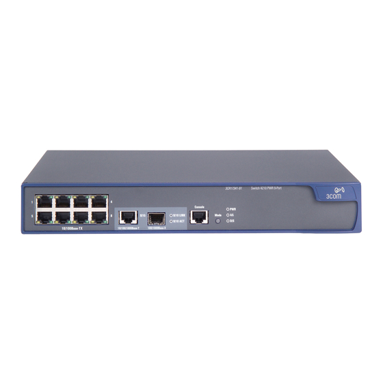
1: P HAPTER RODUCT NTRODUCTION Introduction to the Switch 4210 Family PWR Switches Switch 4210 9-port PWR Front panel Switch 4210s 9-port PWR each provide eight 10/100Base-TX autosensing Ethernet ports, one 10/100/1000Base-T Ethernet port, one 100/1000Base SFP ports, and one Console port. The SFP port and the 10/100/1000BASE-T Ethernet port form a Combo port. - Page 9 Introduction to the Switch 4210 Family PWR Switches If the left screw hole above the security slot is used, the security slot cannot be used. Power system Switch 4210s 9-port PWR support AC input. Rate voltage range: 100 VAC to 240 VAC, 50 Hz/60 Hz ■...
- Page 10 1: P HAPTER RODUCT NTRODUCTION Rear panel Figure 6 Rear panel of an Switch 4210 18-port PWR (1) AC power socket (2) Grounding screw Side panel Each Switch 4210 18-port PWR provides a security slot, through which you can lock the device together with an irremovable object to prevent theft. The security slot is located on the left side panel, as shown in Figure 7.
- Page 11 Introduction to the Switch 4210 Family PWR Switches Switch 4210 PWR 18-Port units are able to power attached devices using standard 802.3af Power over Ethernet. Total available power for PoE on this model is 123W, enough to power 9-Ports at full 15.4W required of the PoE standard. Switch 4210 PWR Front panel 26-port...
- Page 12 They indicate the port’s active, link, duplex, and speed status. In addition, there are an A/L LED and a D/S LED on each model of 3Com Switch 4210 Family PWR. These two LEDs indicate the port status LEDs mode. When the A/L LED is on, the port status LEDs respectively indicate the active status and link status of the ports.
-
Page 13: Introduction To The Switch 4210 Family Non-Pwr Models
Introduction to the Switch 4210 Family Non-PWR Models Table 4 Port status LEDs on the Switch 4210 PWR models Port status mode LED Port status LED Description The A/L LED is Yellow LED BLINKING The port is in the active state and there is (left) traffic on the port. - Page 14 1: P HAPTER RODUCT NTRODUCTION Figure 10 The Switch 4210 9-port model’s front panel (1) 10/100Base-TX autosensing port Speed LED (green) (2) 10/100Base-TX autosensing port (3) Combo port Speed LED (green) (4) 10/100/1000Base-T autosensing port (5) Console port (6) 100/1000Base-X SFP port (7) Link/Act LED (green) (8) Power LED (PWR) Rear panel...
- Page 15 ■ Input voltage range: 90 VAC to 264 VAC, 47 Hz to 63 Hz ■ Cooling system 3Com Switch 4210 non-PWR models have a fanless design cooled from natural airflow. Switch 4210 26-port Front panel The Switch 4210 26-port front panel provides 24 10/100Base-TX autosensing Ethernet ports, two 10/100/1000Base-T autosensing Ethernet ports, two 100/1000Base-X SFP ports, and one Console port.
- Page 16 Rate voltage range: 100 VAC to 240 VAC, 50 Hz/60 Hz ■ Input voltage range: 90 VAC to 264 VAC, 47 Hz to 63 Hz ■ Cooling system 3Com Switch 4210 non-PWR models have a fanless design cooled from natural airflow. The Switch 4210 Family Power LED Front Panel LEDs Table 6 describes the power LED on the Switch 4210.
-
Page 17: Technical Specifications
Technical Specifications Port LED Figure 12 describes the 10/100Base-TX autosensing port’s Link/Act LED. Table 7 The Link/Act LED on the 3Com Switch 4210 Status Description Link/Act LED (green) The port is connected properly. BLINKING The port is in the active state and there is traffic on the port. - Page 18 0°C to 45°C (30°F to 113°F) temperature Relative humidity 10% to 90% (non-condensing) 3Com Switch 4210 Table 11 provides the technical specifications for the Switch 4210 PWR models. Family PWR Table 11 Technical specifications for the Switch 4210 PWR models Switch 4210...
-
Page 19: Sfp Modules Supported For The Switch 4210
3CSFP86 ■ SFP stack module SFP-STACK-Kit The types of SFP modules may vary over time. Consult 3Com marketing ■ personnel or technical support personnel to obtain the latest information about SFP modules. For the SFP module specifications, refer to 3Com Transceiver Data Sheet. - Page 20 1: P HAPTER RODUCT NTRODUCTION...
-
Page 21: Installing The Switch
NSTALLING THE WITCH ® This section contains information that you need to install and set up your 3Com switch. WARNING: Safety Information. Before you install or remove any components from the Switch or carry out any maintenance procedures, you must read the 3Com Switch Family Safety and Regulatory Information document enclosed. -
Page 22: Rack-Mounting The Switch
2: I HAPTER NSTALLING THE WITCH Rack-Mounting the Switch 4210 26-Port models are rack-mountable in a standard 19-inch rack. Switch Switch 4210 9- and 18-Port models are not as wide as the 19-inch model and are intended for desktop or shelf installation. Follow the steps below to mount a 26-Port model unit in a standard 19-inch rack: 1 Check that the rack is sturdy and properly grounded. - Page 23 Rack-Mounting the Switch Figure 18 Mount the front bracket to the mount angel of the rack Screw Screw Front Front bracket bracket Front mount angle Front mount angle Mounting the rear The Switch 4210 26-Port does not need rear brackets. The description for bracket mounting rear brackets is only for the Switch 4210 PWR 24-Port.
-
Page 24: Mounting The Switch On A Desktop
2: I HAPTER NSTALLING THE WITCH Figure 20 Installation completed 1 Screw 2 Screw 2 Screw 1 Screw 1 Rear bracket Rear bracket Rear mount Rear mount angle angle Screw 1: Fix the rear bracket to the mount Screw 2 is mounted to the switch. angle. -
Page 25: Connecting The Power Cords And The Ground Wire
Connecting the Power Cords and the Ground Wire Connecting the Power Cords and the Ground Wire Connecting the AC AC power source socket (recommended) Power Cord Use a single-phase three-wire power socket with a neutral contact or a general purpose PC power socket, making sure that the neutral point is well connected to building ground. - Page 26 2: I HAPTER NSTALLING THE WITCH Figure 23 Ground the switch through a grounding strip ( 2 ) ( 2 ) ( 3 ) ( 3 ) ( 4 ) ( 4 ) ( 1 ) ( 1 ) (1) Power input on the switch (2) Grounding screw on the switch (3) Protection ground wire (4) Grounding strip...
-
Page 27: Connecting Console Cable
Connecting Console Cable Figure 25 Ground through an AC PE wire (1 ) (3 ) (2 ) (2 ) (6 ) (5 ) (4 ) (1) AC power input (2) Grounding screw (3) Power transformer (4) PE ground wire (5) Three-wire AC power input cable (6) Ethernet Switch Connecting Console Cable... - Page 28 2: I HAPTER NSTALLING THE WITCH Connecting Console When you want to use the terminal to configure the switch, follow these steps to Cable connect a terminal device to your switch using console cables: 1 Plug the DB-9 female connector of the Console cable to the serial port of the PC or terminal where the switch is to be configured.
-
Page 29: Setting U P For Management
ETTING P FOR ANAGEMENT To make full use of the features offered by your switch, and to change and monitor the way it works, you have to access the management software that resides on the switch. This is known as managing the switch. Managing the switch can help you to improve the efficiency of the switch and therefore the overall performance of your network. - Page 30 3: S HAPTER ETTING P FOR ANAGEMENT Figure 27 CLI Management using the Console Port Workstation Switch (with terminal emulation software installed) Console Port Connection Console Cable Figure 28 CLI Management over the Network Switch Workstation Connect over Network via Telnet Refer to “Setting Up Command Line Interface Management”...
-
Page 31: Setting Up Overview
You can manage a switch using any network management workstation running the Simple Network Management Protocol (SNMP) as shown in Figure 30. For example, you can use the 3Com Network Director software, available from the 3Com website. Figure 30 SNMP Management over the Network... - Page 32 How do you want to connect to the Switch? configured IP information? Connect to the con- Connect to a front panel port Use 3Com Network Connect to the console sole port and use the and use the Web Interface or Director (3ND).
- Page 33 (Static IP addresses are necessary to ensure that the switch is always allocated the same IP information.) For most installations, 3Com recommends that you assign a known IP address to your switch. This makes management simpler and more reliable as it is not dependent on a DHCP or BootP server, and eliminates the risk of the IP address changing.
-
Page 34: Viewing Automatically Configured Ip Information
Connect a workstation using a console cable to the console port of the switch. You can then view the IP information automatically assigned to the switch using the command line interface (CLI). Network Director or 3Com Network Supervisor ■ These applications will auto-discover the switch and display the automatically allocated IP information assigned to the switch. - Page 35 DHCP or BootP server. If your network does not have a DHCP or BootP server, the workstation running 3Com Network Supervisor or 3Com Network Director must be on the same subnet as the switch, because Auto-IP addresses are non-routable.
-
Page 36: Manually Configuring Ip Information
3: S HAPTER ETTING P FOR ANAGEMENT Manually Configuring You can manually configure the switch IP information in the following ways: IP Information Connecting to the console port ■ Connect a workstation using a console cable to the console port of the switch. You can then manually enter IP information using the command line interface (CLI). - Page 37 Manually Configuring IP Information b Attach the other end of the cable to the workstation and tighten the retaining screws on the cable to prevent it from being loosened. 2 Open your terminal emulation software and configure the COM port settings to which you have connected the cable.
- Page 38 3: S HAPTER ETTING P FOR ANAGEMENT Figure 34 User View Login 3 Enter the system-view command and press Return. To confirm that you are in the System View, the following should be displayed: [4210] Enter interface vlan 1 and Enter. 4 Enter the IP address and subnet mask for the switch as follows: ip address xxx.xxx.xxx.xxx mmm.mmm.mmm.mmm and Enter.
- Page 39 Manually Configuring IP Information Connecting to a Front You can manage your switch, including changing IP address information, by Panel Port making a connection to a front panel port. You can then access the Command Line Interface or the Web interface, as desired. To do this you will need an IP address, refer to “Viewing Automatically Configured IP Information”...
- Page 40 3: S HAPTER ETTING P FOR ANAGEMENT Updating the Switch IP Information You are now ready to review or change the switch with IP information. You can do this using the Web interface or the command line interface (CLI) using telnet. Using the Web Interface 1 Power-up the switch.
-
Page 41: Setting Up Command Line Interface Management
Setting Up Command Line Interface Management Figure 36 User View Login using Telnet 4 Enter the system-view command and Enter. 5 Enter interface vlan 1 and Enter. 6 Enter the IP address and subnet mask for the switch as follows: ip address xxx.xxx.xxx.xxx mmm.mmm.mmm.mmm (where is the IP address and... -
Page 42: Setting Up Command Line Interface Management Using Ssh
<4210>, as shown in Figure 34 on page 38. Setting Up Command To set up command line interface management using SSH, refer to the chapter Line Interface entitled “SSH Terminal Service” in the “3Com® Switch 4210 Family Configuration Management using Guide.” Setting Up Web... -
Page 43: Setting Up Snmp Management
1 (the Default VLAN). By default, all ports on the switch are in VLAN 1. You can use the 3Com Network Supervisor or 3Com Network Director application that is available from the 3Com website to provide SNMP management for your... -
Page 44: Default Users And Passwords
3: S HAPTER ETTING P FOR ANAGEMENT switch. If you use 3Com Network Director it automatically loads the correct MIBs and necessary files onto your workstation. Prerequisites Documentation supplied with the SNMP network management application ■ software. The default read community string is public. The default write community ■... - Page 45 Default Users and Passwords Use the admin default user name (no password) to login and carry out initial switch setup. To set a password for the admin user in the CLI, enter the following from system view: [4210]local-user admin <cr> [4210-luser-admin]password simple xxxxxxxx (where xxxxxxxx is your chosen password).
- Page 46 3: S HAPTER ETTING P FOR ANAGEMENT...
-
Page 47: Problem Solving
If you experience a problem that is not listed here, it may be included in the Support section of the switch 4210 Command Reference Guide on the CD-ROM that accompanies your switch. For Technical Support information, see “Obtaining Support for Your 3Com Products” on page 73. -
Page 48: Solving Problems Indicated By Leds
4: P HAPTER ROBLEM OLVING Solving Problems If the LEDs on the switch indicate a problem, refer to the list of suggested Indicated by LEDs solutions below. The PWR LED does not light Check that the power cable is firmly connected to the switch and to the supply outlet. -
Page 49: Solving Hardware Problems
3 Power cycle the unit. To do this, remove and reconnect the AC mains supply. If another fan failure warning message is generated using the Command Line Interface or the Web interface, return the unit to 3Com. Unit fails, no SNMP fan failure message is received 1 Power cycle the unit. -
Page 50: Solving Communication Problems
The switch has identified that the SFP does not meet the minimum requirements for the switch and has disabled the port. To correct this problem, completely remove the SFP and replace it with a 3Com approved SFP. Error message indicating that the SFP transceiver is faulty To correct this problem, completely remove the SFP and then reinsert it. -
Page 51: Solving Fabric Formation Problems
Solving Fabric Formation Problems another device on your network. 3Com suggests you use addresses in the range 192.168.0.0 to 192.168.255.255 with a subnet mask of 255.255.255.0. These suggested IP addresses are part of a group of IP addresses that have been set aside specially for use ‘in house’... - Page 52 4: P HAPTER ROBLEM OLVING...
-
Page 53: Upgrading Software
Note: If you need a TFTP or FTP server, you can use the TFTP/FTP servers on www.3Com.com. Search for “tftp server”. The applications are located on the link to “3Com Software Library - Utilities for 32 bit Windows”. These applications run on Windows platforms. -
Page 54: Contents Of The Installation File
HAPTER PGRADING OFTWARE Contents of the When you download the Switch 4210 software from the 3Com Web site, you Installation File receive a self-extracting executable file named s3q05_01_00s56.exe or s3q05_01_00s168.exe. This installation file contains the following: End User License (license.txt) ■... - Page 55 Upgrading from the Command Line Interface 0 -rw- 5213253 Apr 27 2000 12:49:41 s3q05_01_00s56c05.app 15240 KB total (10145 KB free) The file system listing may also contain files called topology.top, configuration files (file suffix .def), and Boot ROM file (suffix .btm). 2 Delete any additional files to acquire the maximum space for downloading the new files.
- Page 56 9, 18, or 26). You can save a configuration file using any name, provided it ends with the extension .def. 3Com recommends that you give each of your switches a unique configuration file name so that the unit to which it belongs is clear.
- Page 57 Upgrading from the Command Line Interface TFTP: 7247 bytes sent in 0 second(s). File uploaded successfully. Backing up the Application Files You can back up the application files to the switch’s flash:/ file system or to a TFTP server. To back up the application file to the switch’s flash:/ file system, enter: ■...
- Page 58 5: U HAPTER PGRADING OFTWARE tftp aaa.aaa.aaa.aaa get s3r01_15.btm Some upgrades do not require an upgrade to the Boot ROM firmware, therefore there may not be a new Boot ROM (.btm) file to download. To display the Boot ROM firmware version, in any view enter: display version The switch returns the following: Bootrom Version is 115...
- Page 59 = 2/2/5 ms <4210>ftp 10.0.1.100 Trying 10.0.1.100 ... Press CTRL+K to abort Connected to 10.0.1.100. 220 3Com FTP Server Version 1.1 User(10.0.1.100:(none)) :(FTP User ID) 331 User name ok, need password Password:(password for the FTP user ID) 230 User logged in [ftp] bin 200 Type set to I.
-
Page 60: Configuring The Boot Loader And Updating The Boot Rom Using The Cli
5: U HAPTER PGRADING OFTWARE [ftp]bye 221 Service closing control connection <4210> 9 Configure the switch to boot from the new application code. See “Configuring the Boot Loader and Updating the Boot ROM Using the CLI” on page 60 for instructions. - Page 61 Configuring the Boot Loader and Updating the Boot ROM Using the CLI Please input the file name(*.def)[flash:/3comoscfg-nPort.def](To leave the existing filename unchanged, press the enter key): flash:/3comoscfg-nPort.def exists, overwrite?[Y/N]:y Validating file. Please wait... Now saving current configuration to the device. Saving configuration flash:/3comoscfg-nPort.def.
-
Page 62: Upgrading From The Boot Rom Menu
5: U HAPTER PGRADING OFTWARE Upgrading from the This section describes how to upgrade your switch from the Boot ROM Interface. Boot ROM Menu You should use this method only of the Command Line Interface is not available because when you work within the Boot ROM menu, all traffic through the switch stops. - Page 63 Upgrading from the Boot ROM Menu Clearing the Flash Before upgrading your switch’s software using the Boot ROM Interface, check the Memory Flash contents to ensure that there is enough space to download the new files. To do this: 1 Select option 3 from the Boot menu. All the files in Flash display, for example: File Number File Size(bytes) File Name...
- Page 64 5: U HAPTER PGRADING OFTWARE Are you sure to download file to flash? Yes or No(Y/N) 4 Enter y and the following information is displayed to indicate that the file is downloading: Attached TCP/IP Interface to netdrv0 Attaching network interface lo0...done Loading........done Free flash Space: 10456064 bytes Writing flash......done!
- Page 65 Upgrading from the Boot ROM Menu Example TFTP Upgrade Procedure BOOT MENU 1. Download application file to flash 2. Select application file to boot 3. Display all files in flash 4. Delete file from flash 5. Modify bootrom password 6. Enter bootrom upgrade menu 7.
- Page 66 5: U HAPTER PGRADING OFTWARE 2 Select option 2 to display the following: Load File name: Switch IP address: Server IP address: FTP User Name: FTP User Password: 3 Enter the file name, Switch IP address, Server IP address, and FTP user name and password to display the following: Are you sure to download file to flash? Yes or No(Y/N) 4 Enter y and the following information is displayed to indicate the file is...
-
Page 67: Configuring The Boot Loader Using The Boot Menu
Configuring the Boot Loader Using the Boot Menu Please input the file attribute (main/backup/none):none done! 6 Repeat step 1 to step 5 for each of the remaining files (.app, .btm, and .def files). Choose none when you have completed all downloads. Configuring the Boot This section describes how to configure which .app file the Switch uses to boot Loader Using the Boot... - Page 68 5: U HAPTER PGRADING OFTWARE Enter your choice(0-3): 2 Select option 1 to display the following: Load File name: Switch IP address: Server IP address: 3 Enter the filename (.btm extension), Switch’s IP address, and Server IP address to display the following: Are you sure to update your bootrom? Yes or No(Y/N) 4 Enter y and the following information is displayed to indicate the file is downloading:...
- Page 69 Configuring the Boot Loader Using the Boot Menu Upgrading the Boot To upgrade the Boot ROM firmware from the Boot menu using XModem do the ROM from the Boot following: Menu using XModem 1 From the Boot Menu, select option 6 to display the following: 1.
- Page 70 5: U HAPTER PGRADING OFTWARE...
-
Page 71: Pin - Outs
OUTS Null Modem Cable RJ-45 to RS-232 25-pin Switch 5500 PC/Terminal Cable connector: RJ-45 female Cable connector: 25-pin male/female Screen Screen only required if screen Shell always required Ground Ground required for handshake PC-AT Serial Cable RJ-45 to 9-pin Switch 5500 PC-AT Serial Port Cable connector: RJ-45 female Cable connector: 9-pin female... -
Page 72: Modem Cable
A: P HAPTER OUTS Modem Cable RJ-45 to RS-232 25-pin Switch 5500 RS-232 Modem Port Cable connector: RJ-45 female Cable connector: 25-pin male Screen Shell Screen Ground Ground Ethernet Port RJ-45 10/100 and 1000BASE-T RJ-45 connections. Pin Assignments Table 10 Pin assignments Pin Number 10/100 1000... -
Page 73: Upport For Your
Gain Service your product at: Benefits http://eSupport.3com.com/ 3Com eSupport services are based on accounts that are created or that you are authorized to access. Solve Problems Online 3Com offers the following support tool: 3Com Knowledgebase — Helps you to troubleshoot 3Com products. This ■... -
Page 74: Contact Us
3Com as a separately ordered product. Separately orderable software releases and licenses are listed in the 3Com Price List and are available for purchase from your 3Com reseller. - Page 75 Details about recent configuration changes, if applicable ■ To send a product directly to 3Com for repair, you must first obtain a return materials authorization number (RMA). Products sent to 3Com without authorization numbers clearly marked on the outside of the package will be returned to the sender unopened, at the sender’s...
- Page 76 Italy 800 879489 U.K. 0800 096 3266 You can also obtain support in this region using this URL: http://emea.3com.com/support/email.html You can also obtain non-urgent support in this region at these email addresses: Technical support and general requests: customer_support@3com.com Return material authorization: warranty_repair@3com.com...
-
Page 77: Om Network Management
3NS is configured with intelligent defaults and the ability to detect network misconfigurations. It can also offer optimization suggestions, making this application ideal for network managers with all levels of experience. To find out more about 3Com Network Supervisor and to download a trial version, go to: www.3com.com/3ns... -
Page 78: 3Com Network Director
By using 3ND you can discover, map, and monitor all your 3Com devices on the network. It simplifies tasks such as backup and restore for 3Com device configurations as well as firmware and agent upgrades. -
Page 79: 3Com Enterprise Management Suite
The client-server offering operates on Windows and UNIX (Linux and Solaris) systems. 3Com EMS is available in four packages, varying in the maximum number of devices actively managed. These include SNMP-capable devices such as switches, routers, security switches, the 3Com VCX™ IP Telephony server,... - Page 80 C: 3C PPENDIX ETWORK ANAGEMENT...
Need help?
Do you have a question about the Switch 4210 Series and is the answer not in the manual?
Questions and answers