Brother BAS-342G PS Instruction Manual
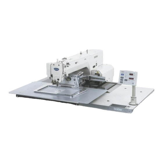
Direct drive programmable electronic pattern sewer, "perfect stitch"
Hide thumbs
Also See for BAS-342G PS:
- Service manual (153 pages) ,
- Manual de instrucciones (86 pages) ,
- Instruction manual (84 pages)

Related Manuals for Brother BAS-342G PS


Summary of Contents for Brother BAS-342G PS
- Page 1 BAS-342G PS INSTRUCTION MANUAL Please read this manual before using the machine. Please keep this manual within easy reach for quick reference. DIRECT DRIVE PROGRAMMABLE ELECTRONIC PATTERN SEWER <PERFECT STITCH>...
- Page 2 Follow the instructions from training personnel and instructors regarding safe and correct operation before operating the machine so that you will know how to use it correctly. BAS-342G PS...
-
Page 3: Safety Instructions
This symbol ( ) indicates something that you must do. The picture inside the circle indicates the ・・・・・・ nature of the thing that must be done. (For example, the symbol at left means “you must make the ground connection”.) BAS-342G PS... - Page 4 Keep the oil out of the reach of children. Be sure to connect the ground. If the ground connection is not secure, you run a high risk of receiving a serious electric shock, and problems with correct operation may also occur. BAS-342G PS...
-
Page 5: Maintenance And Inspection
If any liquid gets inside the sewing machine (machine head or control box), immediately turn off the power and disconnect the power plug from the electrical outlet, and then contact the place of purchase or a qualified technician. BAS-342G PS... - Page 6 Be careful to avoid getting hands caught in sliding parts. Be sure to connect the ground. If the ground connection is not secure, you run a high risk of receiving a serious electric shock, and problems with correct operation may also occur. Direction of operation BAS-342G PS...
- Page 7 Rear cover Thread take-up cover Inside cover R Middle cover Outside cover Eye guard Finger guard Fixed cover Tension release solenoid cover Inside cover L Motor cover Middle cover Outside cover Rear cover Fixed cover X motor cover 2740B BAS-342G PS...
-
Page 8: Table Of Contents
5-5. Installing the bobbin case ......... 23 at once ............50 5-6. Thread tension..........24 5-6-1. Lower thread tension......24 5-6-2. Upper thread tension......24 5-7. Home position detection ........25 5-8. Setting 2-step operation for the work clamp..26 BAS-342G PS... - Page 9 11-10-1. Installing the feed plate ....63 11-11. Adjusting the thread wiper ......63 11-12. Presser foot installation position....64 11-13. Changing the intermittent stroke ....64 11-14. Adjusting the work clamp lift amount.... 66 11-15. Adjusting the air pressure......66 BAS-342G PS...
-
Page 10: Names Of Major Parts
Finger guard Power switch (13) Eye guard Work clamp switch (14) Thread take-up cover Start switch (15) Motor cover Control box Solenoid valve Operation panel Thread wiper switch (10) Pulley (11) Cotton stand is a trademark of SanDisk Corporation. BAS-342G PS... -
Page 11: Specifications
(*1) The number of data items and stitches that can be stored will vary depending on the number of stitches in each program. (*2) Supply of parts relating to 3.5-inch floppy disks has already been discontinued. (However the mechanism will still function.) BAS-342G PS... -
Page 12: Table Processing Diagram
• If using casters, use ones which can bear the total weight of sewing machine and table. • Check that the control box is at least 10 mm away from the leg. If the control box and the leg are too close together, it may result in incorrect sewing machine operation. 4053M BAS-342G PS... -
Page 13: Installation
Carry out the procedures indicated by [1] to [15] in the titles in the order of the numbers. 4-1. Removing the machine head fixing bolts [1] If the sewing machine was already installed to the table when it was delivered, remove the two machine head fixing bolts (1) and the two plain washers (2). 2742B BAS-342G PS... -
Page 14: Installing The Control Box [2]
10mm or more 3962M (6) Power switch (7) Wood screws [2 pcs.] (8) Staples [7 pcs.] NOTE: Take care when tapping in the staples (8) to make sure that they do not pierce the power cord. Operator 3963M BAS-342G PS... -
Page 15: Installing The Oil Pan And Support Lever Base
(b). (1) Rubber bushes (2 pcs.) (2) Hinge holders (2 pcs.) (3) Plain washers [4 pcs.] (4) Spring washers [4 pcs.] (5) Bolts [4 pcs.] 2743B (Continued on next page) BAS-342G PS... -
Page 16: Tilting Back And Returning The Machine Head
If you hold at the place indicated by (b), your hand will get caught between the support lever (1) and the table when the machine head is returned to its original position and injury will result. The machine head can be tilted Disengaging back and returned to one of three the stopper heights. Engaging the stopper 3967M BAS-342G PS... -
Page 17: Installing The Gas Spring
(18) Set screw After installing the gas spring (8), gently return the machine head to its original position. Refer to "4-5. Tilting back and returning the machine head". Note that the L and R shapes are different. 2915B BAS-342G PS... -
Page 18: Installing The Operation Panel [3]
< If the sewing machine was already installed to the table when it was delivered > (1) Operation panel (2) Bolts [3 pcs.] * Pass the cords of the operation panel (1) through the operation panel stand (3) and under the table. 3971M BAS-342G PS... -
Page 19: Installing The Solenoid Valve Assembly
Open valve (4) and air hose (2). 4. Open the cock (1). (The meter pointer will turn clockwise.) NOTE: Turn the cock (1) gently to open it. 5. Adjust the air pressure. (Refer to the next page.) 2747B BAS-342G PS... -
Page 20: Adjusting The Air Pressure [6]
To use, fully tighten both the upper and lower knobs, and then loosen them both by 6 turns. * If the knobs are not at the tightening settings mentioned above, upper thread trimming may not work correctly. BAS-342G PS... -
Page 21: Connecting The Cords [8]
STOP switch 6-pin P13 (HEAD) Valve harness 12-pin P12 (AIR1) Programmer relay harness 8-pin P7 (PRG) Fan 6-pin P10 (SENSOR2) Solenoid selection harness 4-pin P3 (CUTTER) - Thread trimming cylinder sensor harness 16-pin P23 (EX-IN1) 2916B (Continued on next page) BAS-342G PS... - Page 22 P3 (PPM) (5), (6) Thread trimmer solenoid 6-pin P6 (SOL1) (5), (6) Tension release solenoid 4-pin P7 (SOL2) (5), (6) Y pulse motor 4-pin blue P8 (YPM) (5), (6) X pulse motor 4-pin white P10 (XPM) (5), (6) 2568B BAS-342G PS...
-
Page 23: Connecting The Ground Wire [9]
(1) Ground wire from upper shaft motor harness (2) Ground wire from the machine head (3) Ground wire from operation panel (4) Ground wires from two-pedal foot switch harnesses (2 wires) NOTE: Make sure that the ground connections are secure in order to ensure safety. BAS-342G PS... -
Page 24: Securing The Cords And Air Tubes [10]
5. Secure the cover of the control box by tightening the eight screws (5). Check that the cords are not clamped by the cover at this time. 3982M BAS-342G PS... -
Page 25: Installing The Eye Guard [11]
(1) to secure it in place. 2367B 4-17. Installing the cotton stand [12] (1) Cotton stand NOTE: Fit the washer (2), and then securely tighten the nut (3) so that the cotton stand does not move. 3983M BAS-342G PS... -
Page 26: Lubrication [13]
2. Remove the bobbin case and add 2-3 drops of oil to the rotary hook race (2). 3. If using the needle cooler (3), fill it with silicon oil (100 /s). (Refer to "5-3. Threading the upper thread" for details on using the needle cooler (3).) 2752B 2753B 3986M BAS-342G PS... -
Page 27: Connecting The Power Cord [14]
3. Push down the right side of the safety switch (1) so that the safety switch (1) turns on, and then tighten the two screws (2). 4. Turn on the power and check that no error numbers are displayed. 3989M BAS-342G PS... -
Page 28: Preparation Before Sewing
(right side) is then depressed, the sewing machine starts operating. The work clamp (2) lowering method can be changed Work clamp switch using memory switch No. 002. (Refer to "7-3. List of Start switch memory switch settings.") 2755B BAS-342G PS... -
Page 29: Threading The Upper Thread
• When threading the thread through the needle, allow a distance of approximately 45 mm between the needle hole and the end of the thread. If the trailing length of the thread is too long, it may cause the thread to become tangled. BAS-342G PS... -
Page 30: Threading Mode
* When memory switch No. 564 is set to "2", the buzzer will sound after one minute has elapsed, and the tension discs will close. Ending threading mode Press the THREAD/CLAMP key. • The work clamp and the intermittent presser foot will return to the position they were at before threading mode began. THREAD/CLAMP indicator switches off BAS-342G PS... -
Page 31: Winding The Lower Thread
Loosen the set screw (9) and move the bobbin winder tension assembly (10) up and down to adjust. For case A * For case A, move the bobbin winder tension assembly (10) down, and for case B, move it upward. For case B 2775B BAS-342G PS... -
Page 32: Installing The Bobbin Case
5. Clamp the lower thread in the thread hold spring (5). 6. Use the threading bar (6) to pass the thread through the window of the inner rotary hook. (The thread will be released from the thread hold spring (5).) BAS-342G PS... -
Page 33: Thread Tension
1. Turn the tension nut (1) (main tension) to adjust the tension as appropriate for the material being sewn. 2. Use the tension nut (2) (sub tension) to adjust the upper thread trailing length to about 45 mm. Stronger Weaker Stronger Weaker 2573B BAS-342G PS... -
Page 34: Home Position Detection
NOTE: If error "E110" is displayed when the start switch (7) is depressed, turn the pulley (1) in the direction of operation to clear the error display. 4007M 4008M BAS-342G PS... -
Page 35: Setting 2-Step Operation For The Work Clamp
2. With the work clamp (1) raised, loosen the wing screw (2). 3. Move the work clamp stopper (3) to its highest position, and then tighten the wing screw (2) to secure the work clamp stopper (3) in place. 4011M BAS-342G PS... -
Page 36: Using The Operation Panel (Basic Operations)
Used to start threading mode or work clamp height setting mode. (7) THREAD/CLAMP indicator Illuminates when the THREAD/CLAMP key (6) has been pressed. (8) TENSION/WIND key Used to wind the lower thread. (9) TENSION/WIND indicator Used when the digital tension set (option) is installed. BAS-342G PS... - Page 37 (22) Function keys [F1, F2, F3, F4] Used to select user programs and to set and select cycle programs. (23) R/W key Used to read data from and write data to external media. is a trademark of SanDisk Corporation. BAS-342G PS...
-
Page 38: Loading Sewing Data
• The program number will stop flashing and illuminate steadily. NOTE: After completing the setting, be sure to refer to "6-6. Checking the sewing pattern" to check that the needle drop position is correct. 4012M BAS-342G PS... -
Page 39: Setting The X-Scale And Y-Scale
1. Press the SELECT key (1) until the SPEED indicator (2) illuminates. • The setting value (sti/min) will appear in the menu display (3). 2. Press the key (4) to set the sewing speed. (Sewing speed setting: 400 − 2700) 4956Q BAS-342G PS... -
Page 40: Checking The Sewing Pattern
When the start switch (2) is depressed, sewing will start. TEST indicator switches off 4014M If test feeding continues until the Press the TEST key. final stitch, the work clamp will move to the sewing start position and then stop. TEST indicator switches off BAS-342G PS... -
Page 41: Setting The Height Of The Intermittent Presser Foot
When lowered with the needle plate. (Refer to page 64.) Intermittent stroke Refer to "11-13. Changing the intermittent stroke" when making the adjustment. While sewing 2763B BAS-342G PS... -
Page 42: Using The Operation Panel (Advanced Operations)
Production counter setting mode Refer to "7-5. Using the production counter". 4491Q When SPEED indicator is illuminated Production counter temporary display function Refer to "7-5. Using the production counter". 4492Q User program setting mode Refer to "7-7. Using user programs". 4493Q BAS-342G PS... -
Page 43: Setting Memory Switches
RESET key while the number for that memory switch is displayed. • To return the settings for all memory switches to the default settings, keep pressing the RESET key for two or more seconds until the buzzer makes a long beep. BAS-342G PS... -
Page 44: List Of Memory Switch Settings
The larger the value, the more delayed the timing. (*1) The position of the work clamp stopper must be set. (Refer to "5-8. Setting 2-step operation for the work clamp".) (*2) The mm display may differ slightly from the actual sewing size. BAS-342G PS... -
Page 45: Using The Lower Thread Counter
However, this value will not be stored as the initial value. * If a lower thread counter value is set, the lower thread counter will operate even if the lower thread counter is not being displayed. 4963Q BAS-342G PS... -
Page 46: Using The Production Counter
(2). Press the TEST key (6) or the SELECT key (1) to switch the menu back to the normal menu display. * You can start sewing while the temporary display still appears. 4468Q BAS-342G PS... -
Page 47: Setting The Split Number
• Sewing is carried out each time in the order of steps 1 → 2 → 3 → 1 (for example, if there are two sections of split data). [Independent split] Memory switch No. 403 = 2 • The pattern for the displayed split number is sewn independently. BAS-342G PS... -
Page 48: Using User Programs
Press the SELECT key. Press the key to set the X-scale to be recorded. 4470Q X-SCALE indicator flashes Next, set the Y-scale. Press the SELECT key. Press the key to set the Y-scale to be recorded. 4472Q Y-SCALE indicator flashes BAS-342G PS... - Page 49 End user program recording mode. Press the TEST key. This completes the recording of a user program. • The user program number will flash in the PROGRAM No. display. 4971Q TEST indicator switches off, MENU indicator illuminates (Continued on next page) BAS-342G PS...
- Page 50 Press and hold the RESET key for 2 seconds or more. • The buzzer will sound and all user programs will be cleared. NOTE: If any cycle programs have been memorized, all of the memorized cycle programs will also be cleared. BAS-342G PS...
-
Page 51: Using Cycle Programs
2. Press the SELECT key until the desired step is reached. <For cycle programs C-5 to C-9> 1. Press the key to switch the cycle program number. 2. Select the desired cycle program number again, and then press the SELECT key until the desired step is reached. BAS-342G PS... - Page 52 If cycle program sewing mode is active (when memory switch no. 401 is "ON") but no cycle programs have been recorded, the user programs will be sewn in numeric order. “C-0” will appear in the PROGRAM No. display at this time. BAS-342G PS...
-
Page 53: Direct Selection (Combination Table)
U1 to U4 and C-1 to C-4 can be selected using function keys F1 to F4. U5 to U10 and C-5 to C-9 can be selected by simultaneously pressing combinations of function keys F1 to F4 (addition). U5/C-5 U6/C-6 U7/C-7 U8/C-8 U9/C-9 BAS-342G PS... -
Page 54: And Y Parallel Movement Of Sewing Pattern
• In addition, the amount of movement will be reset if the power switch is turned off and then back on again. However, memory switch No. 465 is set to "ON", the amount of movement will be recorded and will not be reset. (Refer to the service manual for details on memory switch No. 465.) BAS-342G PS... -
Page 55: Clearing Memory Data (Reinitialization)
• A long beep will sound and the data for the selected item will be reinitialized. • The setting details for only the initialized item will change from flashing to steadily illuminated. End data initialization mode Press the TEST key. TEST indicator switches off BAS-342G PS... -
Page 56: Using Cf Cards
No. 752 in order to change the folder name. Change the folder name if you would like to store sewing data for different sewing machines on a single CF card. (Refer to the service manual for details on memory switch No. 752.) BAS-342G PS... -
Page 57: Data Read/Write Mode
The sewing data that can be used with this sewing machine is data that has been created for the BAS-300G series. Only valid when using an optional floppy disk drive. Sewing data for the BAS-300 series, BAS-300A series and BAS-300E/F series can be read. Refer to the instruction manual for the programmer for details of expansion option output. BAS-342G PS... -
Page 58: Reading All Sewing Data From The Cf Card At Once
RESET key, the display will change back to [ ALL]. 4976Q Loading End data read/write mode Press the TEST key. Turn off the power switch, remove the CF card, and then close the cover of the CF slot. TEST indicator switches off BAS-342G PS... -
Page 59: Writing All Sewing Data To The Cf Card At Once
End data read/write mode Press the TEST key. Turn off the power switch, remove the CF card, and then close the cover of the CF slot. TEST indicator switches off Refer to the service manual for details on other read/write modes. BAS-342G PS... -
Page 60: Sewing
Use a work clamp and a feed plate which will hold the article securely so that it does not slip. If using the standard work clamp and feed plate and the article being sewn is slipping, take measures to stop the work clamp and feed plate from being slippery. BAS-342G PS... -
Page 61: Using The Stop Switch
Depress the start switch (4). • The sewing machine will start operating and sewing will start. 4022M 9-3. Using the thread wiper switch The thread wiper switch (1) can be used to turn the thread wiper (2) on and off. 4023M BAS-342G PS... -
Page 62: Cleaning
10-3. Checking the regulator 1. If water collects in the bottle of the regulator (1), turn the drain cock (2) in the direction of the arrow to drain the water. 2. After draining the water, tighten the drain cock (2). 2765B BAS-342G PS... -
Page 63: Cleaning The Control Box Air Inlet Ports
10-6. Checking the needle Always check that the tip of the needle is not broken and also that the needle is not bent before starting sewing. 2766B 10-7. Lubrication Lubricate the sewing machine while referring to "4-18. Lubrication". BAS-342G PS... -
Page 64: Standard Adjustments
3. Use a screwdriver to turn the tension stud (5) in order to adjust the tension of the thread take-up spring (3). Stronger Weaker NOTE: If the thread tension spring (3) is not adjusted correctly, the upper thread trailing length will be uneven after thread trimming. BAS-342G PS... -
Page 65: Adjusting Arm Thread Guide R
(3) and then move the needle bar up or down to adjust so that the second reference line from the bottom of the needle bar (reference line A) is aligned with the lower edge of the needle bar bush (1). * If using a DP X 5 needle, use the highest reference line (reference line a). BAS-342G PS... -
Page 66: Adjusting The Needle Bar Lift Amount
If it crosses the needle more than necessary, it will place a load on the needle, or it may cause poor thread tension. Furthermore, if it does not cross the needle at all, the tip of the rotary hook (1) will interfere with the needle and skipped stitches may occur. BAS-342G PS... -
Page 67: Adjusting The Needle Clearance
(1) is tightened as much as possible and then loosened about one turn. • If the adjusting screw (1) is turned clockwise, the lubrication amount becomes smaller. • If the adjusting screw (1) is turned counterclockwise, the lubrication amount becomes greater. 2769B BAS-342G PS... -
Page 68: Adjusting The Position Of The Movable Knife
5. Move the thread trimming rod H (9) forward or back to adjust so that the ridge line on the movable knife (8) and reference line (A) on the needle plate are aligned. 6. After tightening the bolt (7), check the above position once more. BAS-342G PS... - Page 69 (4). In addition, push the driving lever (5) by hand toward the thread trimmer cam (4) until the collar (3) touches the groove of the thread trimmer cam (4), and then check that the driving lever (5) returns smoothly to its original position when it is released. 15. Turn off the power switch. (Continued on next page) BAS-342G PS...
- Page 70 16. Check that there is a gap of about 8.5 – 9.5 mm between the tip of the movable knife (8) and the center of the hole in the needle hole plate (21) when there is still play between the parts. 2917B BAS-342G PS...
-
Page 71: Replacing The Movable And Fixed Knives
7. Apply grease to the pin (12), place it into the movable knife connecting plate (13), and install it to the needle plate (5). 8. Check that the needle is aligned with the center of the needle hole. BAS-342G PS... -
Page 72: Installing The Feed Plate
2 mm and the tip of the thread wiper (2) is approximately 3 mm from the center of the needle when the thread wiper (2) passes below the needle during operation. NOTE: Check that the thread wiper (2) does not touch the finger guard. BAS-342G PS... -
Page 73: Presser Foot Installation Position
(Refer to the next page.) Installation position Intermittent stroke range 2 − 4.5mm 4.5 − 10mm 0 mm (Presser foot does not move up and down) 5012Q BAS-342G PS... - Page 74 <If they are touching> Remove the motor cover (4). Loosen the nut (5), and turn the bolt (6) until it is pressing against the intermittent drive lever (7), and then adjust until the two points mentioned above are not touching. BAS-342G PS...
-
Page 75: Adjusting The Work Clamp Lift Amount
11-15. Adjusting the air pressure Lift up the handle (2) of the regulator (1) and then turn it to adjust the air pressure to 0.5 MPa. After adjustment is complete, push the handle (2) downward to lock it. 2748B BAS-342G PS... -
Page 76: Table Of Error Codes
Turn off the power, and then check if the cutting edges of the fixed knife and movable knife are damaged or worn, and if there are any problems with the thread trimming air cylinder. (Continued on next page) BAS-342G PS... - Page 77 Intermittent presser foot raised or lowered position cannot be detected. E301 Turn off the power, and then check if there are any problems in the intermittent presser foot vertical direction. Problem with work clamp motor home position adjustment data. E303 Re-adjust the home position. BAS-342G PS...
- Page 78 Machine head memory is not connected. E452 Turn off the power, and then check that connector P3 on the power supply motor P.C. board is properly connected. Internal memory is full and copying is not possible. E474 Clear the sewing data. BAS-342G PS...
- Page 79 Check that connector P10 on the main P.C. board is properly connected. If an error code that is not listed above appears or if carrying out the specified remedy does not solve the problem, contact the place of purchase. BAS-342G PS...
-
Page 80: Troubleshooting
Use the programmer to reduce the Thread unravelling at Rotary hook pulls the upper thread at the intermittent presser foot height so that sewing start. sewing start. the upper thread is pressed by the intermittent presser foot at the 1st stitch. BAS-342G PS... - Page 81 Thread jamming. Thread take-up spring tension and Adjust the tension and height of the P. 55 height are incorrect. thread take-up spring. Needle and rotary hook timing is Adjust the needle bar lift amount. P. 57 incorrect. BAS-342G PS...
- Page 82 Smooth the thread path. Upper thread forms the seam poorly. Select the correct intermittent presser foot. Increase the thickness of the feed plate. Clean away the thread scraps and Thread scraps and dust in rotary hook. P. 53 dust. BAS-342G PS...
- Page 83 Safety switch does not work. Adjust the position of the safety switch. P. 18 depressed. If the safety switch is malfunctioning, replace it with a new one. BAS-342G PS...
-
Page 84: Segment Display
14. 7-SEGMENT DISPLAY 0 1 2 3 4 5 6 7 8 9 A B C D E F G H I J K L M N O P Q R S T U V W X Y Z BAS-342G PS... - Page 85 MEMO BAS-342G PS...
-
Page 86: Instruction Manual
INSTRUCTION MANUAL © 2010 Brother Industries, Ltd. All Rights Reserved. BAS-342G PS SB2118-001 E This is the original instructions. 2010.11. B (1)
Need help?
Do you have a question about the BAS-342G PS and is the answer not in the manual?
Questions and answers