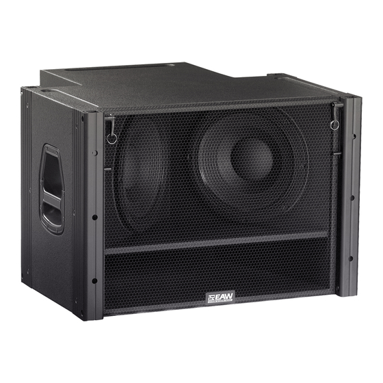
EAW SB730 Owner's Manual
Eaw speaker user manual
Hide thumbs
Also See for SB730:
- Specifications (4 pages) ,
- Dimensions (3 pages) ,
- Declaration of conformity (9 pages)

Subscribe to Our Youtube Channel
Related Manuals for EAW SB730


Summary of Contents for EAW SB730
- Page 1 KF730 & SB730 LOUDSPEAKER OWNER’S MANUAL Including KF730P & SB730P EAW Part: RD0169...
- Page 2 Page 2 of 28 RD0169 (A) KF730 & SB730 OWNER’S MANUAL...
-
Page 3: Table Of Contents
Literature and Specifications ... 25 General ... 25 SERVICE AND MAINTENANCE... 26 General Service ... 26 Rigging Service... 26 Basic Field Troubleshooting ... 26 Inspection ... 26 Maintenance ... 27 TABLE OF CONTENTS Page 3 of 28 RD0169 (A) KF730 & SB730 OWNER’S MANUAL... -
Page 4: Read This First
EAW transactions are made with the assumption that the purchaser is a qualified individual or will have only qualified individuals perform work with the equipment. EAW will not be liable for any damages arising from the use of equipment sold to purchaser. -
Page 5: Introduction
Although EAW will help in any way possible, it is always the responsibility of the receiving party to file any shipping damage claim. The carrier will help prepare and file this claim. -
Page 6: Kf730 Array Design
Use the KF730 Wizard for designing KF730 arrays. It can be found in the Downloads/Software section of the EAW website (www.eaw.com). The Wizard’s primary function is to determine the configuration that will provide the best vertical performance for a given application. Various venue dimensions are entered that allow the Wizard to calculate the resultant array performance. -
Page 7: Ground Stacking
SB730s. 4.4.3 Suspending SB730 Subwoofers The SB730 enclosure rigging is designed to directly couple to a KF730 Fly-Bar and KF730 enclosures. As such, the SB730 can be rigged seamlessly with KF730s. 6 / 4 RD0169 (A) KF730 & SB730 OWNER’S MANUAL Page 7 of 28... - Page 8 KF730 Wizard. When flown separately, SB730s should be flown so that the spacing between the line of SB730 enclosures and KF730 enclosures is about 1 ft / 0.3 m. The SB730 should be suspended in a flat- fronted configuration.
-
Page 9: Array Operation
EAW’s recommended processor settings. KF730 array performance, in terms of frequency response, beamwidth consistency, output level capability, and wavefront coherency is dependent on the EAW engineered crossover and other processing settings. RD0169 (A) KF730 & SB730 OWNER’S MANUAL Page 9 of 28... -
Page 10: Amplifier Gain Settings
The KF730 is a bi-amplified loudspeaker, requiring one LF and one MF/HF amplifier channel. The SB730 has two drivers (SUB 1 and SUB 2) wired separately to the input connectors. This means the drivers can be connected in parallel to a single amplifier channel or each can be connected to a separate amplifier channel. - Page 11 The following tables list the rms voltage limits for the KF730 and SB730. Because of their higher impedance design, multiple KF730s and SB730s can be powered from single amplifier channels. NOTE: The rms Voltage Limit listed for each sub-system (LF, MF/HF, SUB 1/2, or SUB 1 and SUB 2) is the same for any enclosure quantity.
-
Page 12: Input Connections
6 dB, which is usually, but not always, true. Under this condition, the thermal limits are unlikely to be exceeded. While this rule of thumb is consistent with the EAW’s testing parameters, it does NOT guarantee trouble-free operation. That is discussed under “Operating Limits.”... - Page 13 SB730 SYSTEM INPUT on one SB730, an NL8 cable carries all amplified signals from the array’s amplifiers to this SB730. Using NL4 cabling from this SB730, you can loop up to eight KF730s and three additional SB730s. With the maximum combination, the nominal load for each of the four amplified signals is 2 ohms.
- Page 14 50 ft / 15 m > 50 ft / > 15 m (AWG = American Wire Gauge; MWG = Metric Wire Gauge) Page 14 of 28 RD0169 (A) KF730 & SB730 OWNER’S MANUAL MF/HF -- + -- + LOOP THRU...
-
Page 15: Rigging
Because it weighs approximately 111 lb / 51 kg, always use two people or mechanical assistance to lift an SB730. IMPORTANT RIGGING NOTE: Each Quick Release Pin, used to attach enclosures together, can be inserted into one of several holes in both the Hinges and Hinge Tubes integral to the enclosures. -
Page 16: Fly-Bar Rigging Recommendations
Hinge and holes on both sides of each Hinge tube. If properly inserted, a Quick Release Pin will be locked in place and can only be pulled out by pressing the button on its handle. Page 16 of 28 RD0169 (A) KF730 & SB730 OWNER’S MANUAL... - Page 17 Fly-Bar. Two are used as locking pins for the rear Hinges. See “Locking Pins” Section 6.4.5. Each SB730 is supplied with four 1.5 inch Quick Release Pins used for attaching enclosures together or to the Fly-Bar.
- Page 18 Hinge that is captive to that Hinge Tube and below the Hinge knuckle. This prevents the Hinge from receding into its own Hinge Tube, which is what happens when the splay between two enclosures collapses. Page 18 of 28 RD0169 (A) KF730 & SB730 OWNER’S MANUAL Hole 1 Hole 1 FRONT...
-
Page 19: Pallets
6.6.5 SB730 Pallet Place one SB730 or a stack two SB730 enclosures on the pallet oriented right side up. If placing two SB730s on a Pallet, lock the enclosures together by sliding the Hinges from the lower enclosure up into the Hinge Tubes of the upper enclosures. Attach each Hinge to the upper enclosure’s Hinge Tube using the Quick Release Pin from the lower enclosure. -
Page 20: Suspension Procedures
6.7.3 Attaching a KF730 or SB730 to the Fly-Bar 1. Lift the Fly-Bar onto the top of the KF730 or SB730. Orient the Fly-Bar with its corner Hinge Tubes to the front of the loudspeakers. 2. Remove the four (SB730) or six (KF730) Quick Release Pins from the top of the enclosure’s Hinge Tubes. - Page 21 NOTE: SB730s should always be flown tight-packed to each other. 1. Move an SB730 Pallet so its SB730 is positioned under the bottom SB730 of the array. 2. Remove the four Quick Release Pins from the Hinges of the SB730 on the pallet.
-
Page 22: Ground Stacking Procedures
IMPORTANT NOTE: If using one or more SB730s as the stacking base, all KF730 and SB730 enclosures are stacked right side up. Always stack all SB730s underneath the KF730s. 1. At the desired stacking location, position an SB730 on the floor with the Hinges on the top, this being the normal orientation for suspension. - Page 23 CAUTION: When attaching Hinges to Hinge Tubes in step 5 for an SB730, position the SB730 so it lies flat on the SB730 below it. In step 5 for a KF730, use the correct holes as determined by the KF730 Wizard or by the user-desired angles to achieve the desired splay angle. Failure to follow this instruction can result in poor acoustical performance.
- Page 24 CAUTION: When attaching Hinges to Hinge Tubes in step 5 for an SB730, position the SB730 so it lies flat on the SB730 below it. In step 5 for a KF730, use the correct holes as determined by the KF730 Wizard or by the user-desired angles to achieve the desired splay angle. Failure to follow this instruction can result in poor acoustical performance.
-
Page 25: Contacting Eaw
CONTACTING EAW We have tried to answer any questions you may have about the KF730 and SB730 in this manual and in the KF730 Wizard Help file. Should you need further assistance, please do not hesitate to contact us. You can contact us in several different ways. -
Page 26: Service And Maintenance
SERVICE AND MAINTENANCE GENERAL SERVICE For any faults that cannot be field-repaired as noted below, contact the EAW Service Department listed in Chapter 7 to determine the appropriate action. This applies to both warranty and non- warranty faults. RIGGING SERVICE Because of the potential, serious consequences and liabilities due to faulty rigging, contact EAW to determine the appropriate service solution for any rigging hardware problems. -
Page 27: Maintenance
While the enclosure paint finish and wood is of high quality and durability, mars, marks, and other blemishes will likely appear from normal use. For paint touchup, contact the EAW Service Department for original factory paint (Sherwin-Williams Polane® 700T, water reducible polyurethane-acrylic enamel) and instructions for its application. - Page 28 © 2004 EASTERN ACOUSTIC WORKS ONE MAIN STREET WHITINSVILLE, MA 01588 2004 Mar RD0169 Page 28 of 28 RD0169 (A) KF730 & SB730 OWNER’S MANUAL...
Need help?
Do you have a question about the SB730 and is the answer not in the manual?
Questions and answers