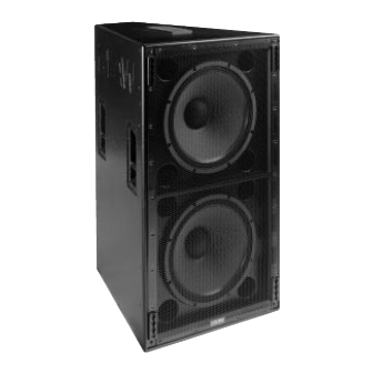
EAW KF755 Series Owner's Manual

EAW KF755 Series Owner's Manual

Hide thumbs Also See for KF755 Series:

Advertisement

K F 7 0 0
S E R I E S
O W N E R ' S
M A N U A L
K F 7 5 0 | K F 7 5 5 | S B 7 5 0

Advertisement

Table of Contents
loading

Summary of Contents for EAW KF755 Series

  • Page 1 K F 7 0 0 S E R I E S O W N E R ’ S M A N U A L K F 7 5 0 | K F 7 5 5 | S B 7 5 0...
  • Page 3: Table Of Contents

    Congratulations on purchasing the latest sound reinforcement innovation from Eastern Acoustic Works. The KF700 Series is built upon the same fundamental design principles that EAW has upheld since the introduction of the KF850 Series of loudspeakers in the 1980’s. This new product line draws elements from Virtual Array Technology™...
  • Page 4: Read This First

    EAW transactions are made with the assumption that the purchaser is a qualified individual or will have only qualified individuals perform work with the equipment. EAW will not be liable for any damages arising from the use of equipment sold to purchaser.
  • Page 5: Unpacking

    Although EAW will help in any way possible, it is always the responsibility of the receiving party to file any shipping damage claim. The carrier will help prepare and file this claim.
  • Page 6: Quick Start

    Section 3 Quick Start NOTE: This section is intended only for qualified professional installers. Important Safety and Rigging Information CAUTION: Read all of Section 1, "Read This First", for important general, safety and rigging precautions. Audio Signal Connections The audio signal connections are via Neutrik NL8 connectors or barrier strips. The two NL8s are wired in parallel.
  • Page 7: Description

    Section 4 Description Overview Professional loudspeaker systems are designed to optimize spectral, spatial, temporal and usability performance attributes. Quite often optimization in one area compromises performance in another. Thus, loudspeaker design is the art of balancing these goals while minimizing compromise. In order to achieve these goals for the KF700 Series, key develop- ments allowed for performance enhancement in each area without compromise in others.
  • Page 8: Operation

    4.1.5 DEFINED The system overview illustrates that the KF700 Series development was driven by enhancing the acoustical performance of the loudspeaker systems as it relates to its arrayability. Each loudspeaker must therefore array effectively both horizontally and vertically. Consistent controlled coverage patterns in three dimensions guarantees predictable array results from venue to venue.
  • Page 9: Input Connections

    Mechanical Characteristics and Accessories 5.3.1 CASTER PALL E T S The KF700 Series includes an optional rugged caster pallet (EAW P/N 255049) designed for years of reliable service in concert touring applications. Caster pallets can be THREE HANDLES FOUR WHEEL CASTERS...
  • Page 10 Weight) plastic stacking pad that keys into the recess in the bottom of another enclosure when stacked. This pad provides for a more secure stack. EAW recommends that fly hard- ware be used to provide additional stability. A crossed configuration of the cable links allows for minimal slack, improving safety and stability.
  • Page 11: Electrical Characteristics And Accessories

    Processor settings for specific array configurations are available in a variety of formats that can be programmed directly into many DSPs. Formats include text lists of parameters as well as processor-specific presets. These settings can be found on the EAW web site: ftp://ftp.eaw.com/Processing/.
  • Page 12: Array Design

    The power handling listed for each EAW transducer is a good indicator of the size of the amplifier that will safely drive it to full output under most conditions. Amplifier selection is dependent upon the load presented at the amplifier output. Each doubling of loud- speaker quantity doubles the required amplifier power.
  • Page 13: System Truck-Pack

    5.5.2 APPROPRIATE HORIZONTAL CONFIGURATION The horizontal coverage angle required for a venue can be readily determined through examination of the plan view. Once the required horizontal coverage has been deter- mined, it is easy to calculate the number of columns required to thoroughly address the entire venue.
  • Page 14: Maintenance And Service

    During the warranty period, EAW will remedy all such defects without charge for parts or labor upon the return of the unit together with its original sales receipt or other proof of purchase to EAW or to an Authorized EAW Service Facility.
  • Page 15: System Maintenance And Repair Tips

    System Maintenance and Repair Tips O B J E C T I V E : This section illustrates the steps to follow when removing the KF700F Series loudspeaker components. To replace the components and reassemble the loudspeaker, reverse these instructions. TA B L E O F C O N T E N T S : Section 6.3.1 KF750F ......9...
  • Page 16 6.3.1.2 Removing the High Frequency Horn Assembly: This assembly is heavy. It is made up of a metal bracket, a horn and a driver with 2 elec- trical leads. The leads must be disconnected carefully. • While supporting the assembly, remove the mounting screws that hold the assembly into the cabinet with a 3/16 allen wrench.
  • Page 17 • Lift the woofer from the cabinet. • Flip the cabinet and repeat the above steps for the second woofer. 6.3.1.4 Removing the Doghouse: To access the mid frequency driver/phase plug assembly, remove the doghouse. • Remove the 10 phillips head screws that attach the doghouse to the loudspeaker cabinet (5 per side, indicated by the arrows).
  • Page 18: Kf750P

    6.3.1.5 Removing the Phase Plug Assembly: • Remove the 4 phillips head screws, lock washers and flat washers. This assembly is heavy and must be supported during removal. Do not discard the mounting hardware. KF750F CABINET WITH DOG HOUSE REMOVED KF750 PHASE PLUG ASSEMBLY 251147 4X WASHER 1/4...
  • Page 19 • Remove the 4 screws and washers from the center of the grille with a 5/32 allen wrench. These attach the front of the internal high frequency horn to the grille. • Remove the16 grille mounting screws and washers from the outside edge with a phillips head screwdriver.
  • Page 20: Kf750P-Wp

    After removing the 22 mounting screws, carefully move the doghouse to access the phase plug assembly. The internal electrical wires that connect the components are short in length and must be handled carefully. • Remove the yellow lead + from the red pushbutton terminal on the phase plug assembly.
  • Page 21 WIRE MESH STAINLESS STEEL GRILLE 702381-0002 4X HORN MOUNTING GRILLE SCREWS 1/4-20 X 1 LG BLACK 104023 (ONLY 2 SHOWN) USE 5/32 ALLEN HEAD WRENCH 4X WASHERS 1/4 NYLON BLACK 105065 (ONLY 2 SHOWN) 16X GRILLE SCREWS #8 X 5/8"LG PHILLPS HEAD BLACK 102102 (ONLY 7 SHOWN) GRILLE FOAM 712028...
  • Page 22: Kf755F

    6.3.3.2 Removing the High Frequency Horn Assembly: Refer to Section 6.3.1.2. 6.3.3.3 Removing the Two Woofers: Refer to Section 6.3.1.3. 6.3.3.4 Disconnecting the Doghouse: Refer to Section 6.3.2.4. 6.3.3.5 Removing the Phase Plug Assembly: Refer to Section 6.3.1.5. 6.3.3.6 Disassembling the Phase Plug Assembly: Refer to Section 6.3.1.6.
  • Page 23 6.3.4.2 Removing the High Frequency Horn Assembly: This assembly is heavy, made up of a horn, a metal bracket, 2 metal standoffs, and a driver with two electrical leads. The leads must be disconnected carefully. • Remove the phillips head screw and lock washer that attaches the top and bottom supports to the cabinet.
  • Page 24 6.3.4.4 Removing the Doghouse: To access the mid frequency driver/phase plug assembly, remove the doghouse. • Remove the 10 phillips head screws that attach the doghouse to the back of the loudspeaker cabinet (5 per side, indicated by the arrows). KF755F DOGHOUSE 508001...
  • Page 25: Kf755P

    KF755F CABINET WITH DOG HOUSE REMOVED KF750 PHASE PLUG ASSEMBLY 251147 4X WASHER 1/4 FLAT 105007 4X WASHER 1/4 LOCK 105008 4X SCREW 1/4-20 X 3/4 LG PHILIPS PAN HEAD 102039 6.3.4.6 Disassembling the Phase Plug Assembly: Refer to Section 6.3.1.6. 6.3.4.7 Reinstallation of KF750F Components: To reinstall any of the components listed in this section, reverse the appropriate...
  • Page 26 6.3.5.2 Removing the High Frequency Horn Assembly: Refer to Section 6.3.4.2. 6.3.5.3 Removing the Woofer: Refer to Section 6.3.4.3 6.3.5.4 Disconnecting the Doghouse: To access the mid frequency driver/phase plug assembly, remove the doghouse. • Remove the 22 phillips head screws that attach the doghouse to the loudspeaker cabinet.
  • Page 27: Kf755P-Wp

    6.3.5.7 Reinstallation of KF755P Components: To reinstall any components mentioned in this section, reverse the appropriate disas- sembly instruction. 6.3.6 KF755P-WP LOUDSPEAKER PROCEDURE: 6.3.6.1 Accessing the Woofer Chamber: Remove the grille, grille foam and wire mesh. • Remove the 16 grille mounting screws with a phillips head screwdriver. During removal, hold the grille, grille foam and wire mesh in place.
  • Page 28: Sb750F

    6.3.7 SB750F LOUDSPEAKER PROCEDURE: 6.3.7.1 Accessing the Woofer Chamber: Remove the grille/grille foam assembly. • During removal, hold the grille/grille foam assembly in place. This prevents the grille foam from tearing. • Remove the 18 grille mounting screws and washers with a 5/32 allen wrench. Do not discard the hardware.
  • Page 29: Sb750P

    • Remove the 8 woofer mounting screws with a 3/16 allen wrench. Do not discard the mounting hardware. • Lift the woofer from the cabinet only enough to access and disconnect the blue lead+ from the red pushbutton terminal, and the black lead– from the black push- button terminal.
  • Page 30: Sb750P-Wp

    6.3.9 SB750P-WP LOUDSPEAKER PROCEDURE: 6.3.9.1 Accessing the Woofer Chamber: Remove the grille, grille foam and wire mesh. Be careful handling the wire mesh; it can easily cut into the skin. • During removal, hold the grille, grille foam and wire mesh in place. This prevents the grille foam from tearing.
  • Page 31: Specifications

    Section 7 Specifications M O D E L K F 7 5 0 K F 7 5 5 Configuration 3-way, full range 3-way, full range Powering triamplified (MX8600 processor) triamplified (MX8600 processor) Drivers: (2) 12 in cones, dipolar array, vented 12 in cone, vented 10 in cone, radial phase plug, horn-loaded 10 in cone, radial phase plug, horn-loaded...
  • Page 32 One Main Street, Whitinsville, MA 01588 tel: 800 992 5013 / 508 234 6158 fax: 508 234 8251 web: www.eaw.com PN 425013 (0) EAW is the worldwide technological and market leader in the design and manufacture of high-performance, professional loudspeaker systems.

This manual is also suitable for:

Sb750 seriesKf750 series

Table of Contents