Table of Contents
Advertisement
P4M890-M7 SE Setup Manual
FCC Information and Copyright
This equipment has been tes ted and found to comply with the limits of a Class
B digital devic e, purs uant to Part 15 of the FCC Rules . T hese limits are designed
to provide reasonable protec tion against harmful interference in a residential
installation. T his equipment generates , uses and can radiate radio frequency
energy and, if not ins talled and used in accordance with the instructions , may
cause harmful interference to radio communications . There is no guarantee
that interference will not occur in a particular ins tallation.
The vendor makes no representations or warranties with respec t to the
contents here and s pecially disclaims any implied warranties of merchantability
or fitness for any purpose. Further the vendor reserves the right to revise this
publication and to make c hanges to the c ontents here without obligation to
notify any party beforehand.
D uplication of this publication, in part or in whole, is not allowed without first
obtaining the vendor's approval in writing.
The content of this user's manual is subject to be c hanged without notice and
we will not be res ponsible for any mis takes found in this user's manual. All the
brand and produc t names are trademarks of their respec tive companies .
Advertisement
Chapters
Table of Contents

Related Manuals for Biostar P4M890-M7 SE


Summary of Contents for Biostar P4M890-M7 SE
- Page 1 P4M890-M7 SE Setup Manual FCC Information and Copyright This equipment has been tes ted and found to comply with the limits of a Class B digital devic e, purs uant to Part 15 of the FCC Rules . T hese limits are designed to provide reasonable protec tion against harmful interference in a residential installation.
-
Page 2: Table Of Contents
Table of Contents Chapter 1: Introduction ..........3 Before You Start..............3 Package Checklist..............3 Motherboard Features............4 Rear Panel Connectors............5 Motherboard Layout ............6 Chapter 2: Hardware Installation......7 Installing Central Processing Unit (CPU) ........ 7 FAN Headers................ 9 Installing System Memory.............10 Connectors and Slots ............11 Chapter 3: Headers &... -
Page 3: Chapter 1: Introduction
P4M890-M7 SE CHAPTER 1: INTRODUCTION EFORE T ART Thank you for choosing our product. Be fore you start installing the mothe rboard, please make sure you follow the instructions be low: Prepare a dry and stable work ing environment with sufficie nt lighting. -
Page 4: Motherboard Features
Motherboard Manual OT HERBOARD EAT URES SPEC LGA 775 Intel Core 2Duo/ Pe ntium 4 / Pe ntium D / Supports Hy per Tra nsport/ Execute Disable Celeron D pr ocessor up to 3.8 GHz Bit/ Enhanced Intel S peedStep®/ Intel *It is recommende d to use processors Extende d Memor y 64 technolo gy with 95W power consumption. -
Page 5: Rear Panel Connectors
Provide A udio-I n/Out a nd micropho ne connection Board Size 190 mm (W) x 244 mm (L) Micro ATX form Factor Biostar Reserves the right to a dd or r emove Windows 2000 / XP Support support for any OS with or witho ut notice. -
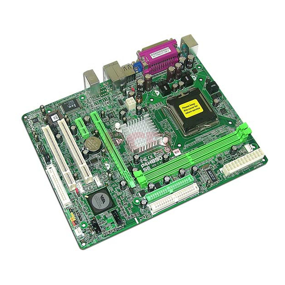
Page 6: Motherboard Layout
Motherboard Manual OT HERBOARD AYOUT JCFAN1 J KBMS 1 LGA775 CPU1 JATXPWR1 JUSB1 JUSBV1 JATXPWR2 P4M890 JUSBLAN1 J AUDIO1 PCI-EX16 BAT1 Super PCI-EX1_1 JSATA2 JUSB2 PCI1 VT8237A BIOS JSATA1 JCDIN1 JUSB3 PCI2 JUSBV2 JCMOS1 JSPDIF_OUT1 Codec FDD1 JSFAN1 JAUDIOF1 JPANEL1 Not e: represe nts the 1 pin. -
Page 7: Chapter 2: Hardware Installation
P4M890-M7 SE CHAPTER 2: HARDWARE INSTALLATION (CPU) NST ALLING ENT RAL ROCESSING Special Notice: Remove Pin Cap before installation, and make good preservation for future use. When the CPU is removed, cover the Pin Cap on the empty socket to ensure pin legs won’t be damaged. - Page 8 Motherboard Manual Step 2: Look for the triangular cut edge on socket, and the golden dot on CPU should point forwards this triangular cut edge. The CPU will fit only in the correct orientation. Step 2-1: Step 2-2: Step 3: Hold the CPU down firmly, and then lower the lever to locked position to complete the installation.
-
Page 9: Fan Headers
P4M890-M7 SE FAN H EADERS These fan headers support cooling-fans built in the computer. The fan cable and connector may be different according to the fan manufacturer. Connect the fan cable to the connector while matching the black wire to pin#1. -
Page 10: Installing System Memory
Motherboard Manual NST ALLING YST EM EMORY A. Memory Modules Unlock a DIMM slot by pressing the retaining clips outward. Align a DIMM on the slot such that the notch on the DIMM matches the break on the Slot. Insert the DIMM vertically and firmly into the slot until the retaining chip snap back in place and the DIMM is properly seated. -
Page 11: Connectors And Slots
P4M890-M7 SE ONNECT ORS AND LOT S FDD1: Floppy Disk Conne ctor The motherboard prov ides a standard floppy disk connector that supports 360K, 720K, 1.2M, 1.44M and 2.88M floppy disk ty pes. This connector supports the prov ided f loppy drive ribbon cables. - Page 12 Motherboard Manual PCI-EX16: PCI-Express x16 Slot PCI-Express 1.0a compliant. Maximum theoretical realized bandwidth of 4GB/s simultaneously per direction, f or an aggregate of 8GB/s totally. PCI-EX1_1: PCI-Express x1 Slot PCI-Express 1.0a compliant. Data transf er bandwidth up to 250MB/s per direction; 500MB/s in total. PCI-Express supports a raw bit-rate of 2.5Gb/s on the data pins.
-
Page 13: Chapter 3: Headers & Jumpers Setup
P4M890-M7 SE CHAPTER 3: HEADERS & JUMPERS SETUP OW T O ET UP UMPERS The illustration shows how to set up jumpers. When the jumper cap is placed on pins, the jumper is “close”, if not, that means the jumper is “open”. - Page 14 Motherboard Manual ATX Powe r Source Conne ctor: JATXPWR1 JATXPWR1 allows user to connect 24-pin power connector on the ATX power supply. Assignment Assignment +3.3V +3.3V -12V +3.3V Ground Ground PS_ON Ground Ground Ground Ground Ground PW_OK Standby Voltage+5V +12V +12V Ground +3.3V...
- Page 15 P4M890-M7 SE JUSB2/JUSB3: Heade rs for USB 2.0 Ports at Front Panel This header allows user to connect additional USB cable on the PC f ront panel, and also can be connected with internal USB devices, like USB card reader.
- Page 16 Motherboard Manual JAUDIO F1: Front Panel Audio Heade r This header allows user to connect the front audio output cable with the PC f ront panel. It will disable the output on back panel audio connectors. Assignment Mic Left in Ground Mic Right in GPIO...
-
Page 17: Serial Ata Connectors
P4M890-M7 SE JCMO S1: Cle ar CMOS Heade r By placing the jumper on pin2-3, it allows user to restore the BIOS saf e setting and the CMOS data, please carefully f ollow the procedures to avoid damaging the motherboard. -
Page 18: Chapter 4: Useful Help
Motherboard Manual CHAPTER 4: USEFUL HELP RIVER NST ALLAT ION OT E After you installed your operating system, please insert the Fully Setup Driver CD into your optical drive and install the driver for better system performance. You will see the following window after you insert the CD The setup guide will auto detect your motherboard and operating system. -
Page 19: Award Bios Beep Code
BIOS contents are corrupted. In this Case, please follow the procedure below to restore the BIOS: 1. Make a bootable floppy disk. 2. Download the Flash Utility “AWDFLASH.exe” from the Biostar website: www.biostar.com.tw 3. Confirm motherboard model and download the respectively BIOS from Biostar website. - Page 20 Motherboard Manual B. CPU Overheated If the system shutdown automatically after power on system for seconds, that means the CPU protection function has been activated. When the CPU is over heated, the motherboard will shutdown automatically to avoid a damage of the CPU, and the system may not power on again.
-
Page 21: Troubleshooting
P4M890-M7 SE 4.4 T ROUBLESHOOT ING Probable Solution No power to the system at all Make sure power cable is Power light don’t illuminate, f an securely plugged in. inside power supply does not turn Replace cable. Contact technical support. -
Page 22: Chapter 5: Warpspeeder
Motherboard Manual WARPSPEEDER™ CHAPTER 5: NT RODUCT ION [WarpSpeeder™], a new powerful control utility, features three user-friendly functions including Overclock Manager, Overvoltage Manager, and Hardware Monitor. With the Overclock Manager, users can easily adjust the frequency they prefer or they can get the best CPU performance with just one click. The Overvoltage Manager, on the other hand, helps to power up CPU core voltage and Memory voltage. -
Page 23: Installation
P4M890-M7 SE NST ALLAT ION 1. Execute the setup execution file, and then the following dialog will pop up. Please click “Next” button and follow the default procedure to install. 2. When you see the following dialog in setup procedure, it means setup is completed. -
Page 24: Warpspeeder
Motherboard Manual ™ PEEDER 1. Tray Icon: Whenever the Tray Icon utility is launched, it will display a little tray icon on the right side of Windows Taskbar. This utility is responsible for conveniently invoking [WarpSpeeder™] Utility. Y ou can use the mouse by clicking the left button in order to invoke [WarpSpeeder™] directly from the little tray icon or you can right-click the little tray icon to pop up a popup menu as following figure. - Page 25 P4M890-M7 SE 2. Main Panel If you click the tray icon, [WarpSpeeder™] utility will be invoked. Please refer to the following figure; the utility’s first window you will see is Main Panel. Main Panel contains fe ature s as follows: a.
- Page 26 Motherboard Manual 3. Voltage Panel Click the Voltage button in Main Panel, the button will be highlighted and the Voltage Panel will slide out to up as the following figure. In this panel, you can decide to increase CPU core voltage and Memory voltage or not.
- Page 27 P4M890-M7 SE 4. Overclock Panel Click the Overclock button in Main Panel, the button will be highlighted and the Overclock Panel will slide out to left as the following figure. O ve rclock Panel contains the these features: a. “–3MHz button”, “-1MHz button”, “+1MHz button”, and “+3MHz button”: provide user the ability to do real-time overclock adjustment.
- Page 28 Motherboard Manual “Auto-overclock button”: User can click this button and [WarpSpeeder™] will set the best and stable performance and frequency automatically. [W arpSpeeder™] utility will execute a series of testing until system fail. Then system will do fail-safe reboot by using Watchdog function. After reboot, the [WarpSpeeder™] utility will restore to the hardware default setting or load the verified best and stable frequency according to the Recovery Dialog’s setting.
- Page 29 P4M890-M7 SE 6. About Panel Click the “about” button in Main Panel, the button will be highlighted and the About Panel will slide out to up as the following figure. In this panel, you can get model name and detail information in hints of all the chipset that are related to overclocking.
-
Page 30: Appendencies: Spec In Other Language
Motherboard Manual APPENDENCIES: SPEC IN OTHER LANGUAGE ERMAN Spezifikationen LGA 775 Intel Core2Duo/ Pe ntium 4 / Pe ntium D Unterstützt Hyper-Threa ding / Execute Disable / Celeron D Prozessoren mit bis zu 3,8 Bit / Enhance d I ntel Spee dStep® / Intel Architecture-64 / Exte nde d Memory 64 *It is recommende d to use processors Technol ogy... - Page 31 Druckeranschluss VGA-Anschluss LAN-Anschluss USB-Anschluss Audioanschluss Platinengr ö 190 mm (B) X 244 mm (L) ße. Biostar behält sich das Recht v or, ohne OS-Unterst Ankündigung die Unterstützung für ei n Windows 2K / XP ützung Betriebssystem hinzuzufügen oder zu entfernen.
-
Page 32: France
Motherboard Manual RANCE SPEC LGA 775 Processeurs Intel Core 2Duo/ P entium Prend en charge les technologies 4 / Pe ntium D / Celer on D jusqu'à 3,8 Hyper -Thre ading / d'ex écution de bit de désactivation / I ntel Spe edStep® optimisée/ *It is recommende d to use processors d'architecture Intel 64 / de mém oire éte ndue 64 with 95W power consumption. - Page 33 Port USB Fiche audio Dimension s de la 190 mm (l) X 244 mm (H) carte Support Biostar se réserve le droit d'ajo uter o u de Windows 2K / XP supprimer le support de SE av ec ou sans préavis.
-
Page 34: Italian
Motherboard Manual T ALIAN SPECIFICA LGA 775 Processore Intel Core 2Duo/ Pentium Supporto di Hyper -Threadi ng / Execute Disable 4 / Pentium D / Celero n D fino a 3.8 Bit / Enhance d I ntel Spee dStep® / Architettura Intel 64 / Tecnologia Exte nde d Memory 64 *It is recommende d to use processors with 95W power consumption. - Page 35 Porta USB Connettore audio Dimension 190 mm (larghezza) x 244 mm i scheda (altezza) Sistemi Biostar si riserva il diritto di aggiungere o Windows 2K / XP operativi rimuovere il supporto di qualsiasi sistema supportati operativo se nza pre avviso.
-
Page 36: Spanish
Motherboard Manual PANISH Especificación LGA 775 Procesador I ntel Core 2Duo/ P entium Admite Hyper -Threadi ng / Bit de deshabilitación de ejecució n / Intel SpeedStep® Me jorado / Intel 4 / Pentium D / Celero n D hasta 3,8 Architecture-64 / Tecnologí... - Page 37 Conector de sonido Tamaño de 190mm. (A) X 244 Mm. (H) la placa Soporte de Biostar se reserva el derecho de aña dir o r etirar el sistema Windows 2K / XP soporte de cualquier SO con o sin aviso previo. operativo...
-
Page 38: Portuguese
Motherboard Manual ORT UGUESE ESPECIFICAÇÕ ES LGA 775 Processador Intel Cor e2Duo/ Pentium Suporta as tecnologias Hyper -Threa ding / Execute Disable Bit / Enhanced I ntel SpeedStep® 4 / Pentium D / Celero n D até 3,8 GHz *It is recommende d to use processors / Intel Arquitecture - 64 / Extended Memory 64 with 95W power consumption. - Page 39 Tomada de áudio Tamanho 190 mm (L) X 244 mm (A) da pl aca Sistemas A Biostar reserva-se o direito de adicionar ou operativos Windows 2K / XP remover suporte par a qual quer sistema operativo suportado com ou sem aviso pré vio.
-
Page 40: Polish
Motherboard Manual OLISH SPEC LGA 775 Obsługa Hy per-Thre ading / Execute Disabl e Bit / Procesor Intel Core 2Duo/ P entium 4 / Enha nced Intel SpeedStep® / I ntel Procesor Pentium D / Celeron D do 3,8 GHz Architecture-64 / Exte nde d Memory 64 *It is recommende d to use processors Technol ogy... - Page 41 Port druk arki Port VGA Port LAN Port USB Gniazdo audio Wymiary 190 mm (S) X 244 mm (W) płyty Obsluga Biostar zastrzega sobie prawo do dawania lub systemu Windows 2K / XP odwoływania obsługi dowolnego systemu operacyjn operacyjnego bez powiadomie nia.
-
Page 42: Russian
Motherboard Manual USSIAN СПЕЦ. LGA 775 Подде ржка техноло гий Hy per-Thre ading / (центра ль Процессор Intel Core 2Duo/ Pe ntium Execute Disable Bit / Enhanced I ntel SpeedStep® ный 4 / Pentium D / Celero n D до 3.8 ГГц / Intel Architecture- 64 / Extended M emory 64 процессор... - Page 43 наушников Размер 190 мм (Ш) X 244 мм (В) пане ли Biostar сохраня ет за собо й прав о добав лять Подде ржк Windows 2K / XP или уда лять сре дства обес пече ния для OS с а OS...
-
Page 44: Arabic
Motherboard Manual RABIC اﻟﻤﻮاﺻﻔﺎت LGA 775 ﻡﻌﺎﻟﺠﺎتIntel Core2Duo/ Penti um 4 / Hyper -Thr eadi ng / Ex ecute Disa ble Bit ﺎت ﺕﺪﻋﻢ ﺕﻘﻨﻴ Pentium D / Celeron D ﺼﻞ إﻟﻰ ﻳ ﺘﺮدد ﺑ اﻟﻤﻌﺎﻟﺠﺔ وﺣﺪة / Enha nced I ntel Spee dStep® / Exte nde d ﺝﻴﺠﺎ... - Page 45 P4M890-M7 SE اﻟﻤﻮاﺻﻔﺎت ﻋﺪد ﻡﻨﻔﺬ ﻡﺤﺮك أﻗﺮاص ﻡﺮﻥﺔ اﻟﻤﺮﻥﺔ ﻟﻸﻗﺮا ص ﻡﺤﺮآﻴﻦ ﻳﺪﻋﻢ ﻋﺪد ﻡﻨﻔﺬ أﺝﻬﺰة ﻡﻦ اﺙﻨﻴﻦ ﻡﻨﻔﺬ آﻞ ﻳﺪﻋﻢ SATA ﻋﺪد SATA ﻡﻨﻔﺬ أﺝﻬﺰة ﻡﻦ واﺣﺪ ﻡﻨﻔﺬ آﻞ ﻳﺪﻋﻢ ﻋﺪد ﻡﻨﻔﺬ اﻟﻠﻮﺣﺔ اﻷﻡﺎﻡﻴﺔ اﻷﻡﺎﻡﻴﺔ اﻟﻠﻮﺣﺔ ﺕﺠﻬﻴﺰات ﻳﺪﻋﻢ ﺪد...
-
Page 46: Japanese
Motherboard Manual APANESE 仕様 LGA 775 Hyper -Thre ading / Exec ute Disabl e Bit / Intel Core2Duo/ Pe ntium 4 / Pentium Enha nced Intel SpeedStep® / I ntel D / Celeron D processor up to 3.8 GHz Architecture-64 / Exte nde d Memory 64 *It is recommende d to use processors Technol ogy をサポートします... - Page 47 P4M890-M7 SE 仕様 各コネクタは2つのフロッピードライブをサポートし フロッピーコネクタ ます IDEコネクタ 各コネクタは2つのIDEデバイスをサポートします SATAコネクタ 各コネクタは1つのSATAデバイスをサポートします フロントパネルコネクタ フロントパネル機能をサポートします フロントオーディオコネクタ フロントパネルオーディオ機能をサポートします CDインコネクタ CDオーディオイン機能をサポートします オンボード S/PDIFアウトコネクタ デジタルオーディオアウト機能をサポートします コネクタ CPUファンヘッダ CPUファン電源装置(スマートファン機能を搭載) システムファンヘッダ システムファン電源装置 CMOSクリアヘッダ 各コネクタは2つのフロントパネルUSBポートをサポ USBコネクタ ートします 電源コネクタ(24ピン) 電源コネクタ(4ピン) PS/2キーボード PS/2マウス シリアルポート 背面パネル プリンタポート VGAポート LANポート USBポート オーディオジャック ボードサイ...
- Page 48 P4M890-M7 SE BIOS Setup BIOS Setup ....................1 1 Main Menu....................3 2 Standard CMOS Features..............7 3 Advanced BIOS Features ...............9 4 Advanced Chipset Features..............17 5 Integrated Peripherals................21 6 Power Management Setup..............27 7 PnP/PCI Configurations...............32 8 PC Health Status ...................35 9 Performance Booster Zone..............37...
-
Page 49: Bios Setup
P4M890-M7 SE BIOS Setup Introduction The purpose of this manual is to describe the settings in the Phoenix-Award™ BIOS Setup program on this motherboard. The Setup program allows users to modify the basic system configuration and save these settings to CMOS RAM. -
Page 50: Acpi Support
P4M890-M7 SE ACPI Support Phoenix-Award ACPI BIOS support Version 1.0b o f Advan ced Con figuration and Power interface speci fi cation (ACPI). It provides ASL code for power management and devi ce con figu ration cap abilities as defined in the ACPI speci fication, developed by Microsoft, Intel and Toshiba. -
Page 51: Main Menu
P4M890-M7 SE 1 Main Menu Once you enter Phoenix-Award BIOS™ CMOS Setup Utility, the Main Menu will appear on the screen. The Main Menu allows you to select from several setup functions. Use the arrow keys to select among the items and press <Enter>... -
Page 52: Load Optimized Defaults
P4M890-M7 SE Advanced Chipset Features This submenu allows you to configure special chipset featu res. Integrated Peripherals This submenu allows you to configure cert ain IDE hard drive options and Programmed Input/ Output features. Power Management Setup This submenu allows you to configure the power managem ent features. -
Page 53: Set Supervisor Password
P4M890-M7 SE Set Supervisor Password Setting the supervisor password will prohibit everyone except the supervisor from making changes using the CMOS Setup Utility. You will be prompted with to enter a password. Set User Password If the Supervisor Password is not set, then the User Password will function in the same way as the Supervisor Password. - Page 54 P4M890-M7 SE Upgrade BIOS This submenu allows you to upgrade bios.
-
Page 55: Standard Cmos Features
P4M890-M7 SE 2 Standard CMOS Features The items in Standard CMOS Setup Menu are divided into several categori es. Each category includes no, one or more than one setup items. Use the arrow keys to highlight the item and then use the<PgUp> or <PgDn> keys to select the value you want in each item. - Page 56 P4M890-M7 SE Item Options Description Press <Enter> to enter the Options are in its sub IDE Channel 1 Master sub menu of detailed menu. options. Press <Enter> to enter the Options are in its sub IDE Channel 1 Slav e sub menu of detailed menu.
-
Page 57: Advanced Bios Features
P4M890-M7 SE 3 Advanced BIOS Features Figure 3: Advanced BIOS Setup Boot Seq & Floppy Setup This item allows you to setup boot sequence & Floppy. -
Page 58: Hard Disk Boot Priority
P4M890-M7 SE Hard Disk Boot Priority The BIOS will attempt to arrange the Hard Disk boot sequence automatically. You can change the Hard Disk booting sequence here. The Choices: Pri. Master, Pri. Slave, Sec. Master, Sec. Slave, USB HDD0, USB HDD1, USB HDD2, and Bootable Add-in Cards. - Page 59 P4M890-M7 SE Boot Up Floppy Seek When enabled, System will test the floppy drives to determine if they have 40 or 80 tracks during boot up. Disabling this option reduces the time it takes to boot-up. The Choices: Enabled (default), Disabled.
- Page 60 P4M890-M7 SE Cache Setup CPU L1 & L2 Cache Depending on the CP U/chipset in use, you may be able to increase me mory access time with this option. Enabled (default) Enable cache. Disabled Disable cache. CPU L3 Cache Depending on the CP U/chipset in use, you may be able to increase me mory access time with this option.
-
Page 61: Cpu Feature
P4M890-M7 SE CPU Feature Delay Prior to Thermal Set this item to enable the CP U Thermal function to engage after the specified time. The Choices: 4 Min, 8 Min, 16Min (default), 32 Min. Thermal Management This option allows you to select the way to control the “ Thermal Management.”... -
Page 62: Virus Warning
P4M890-M7 SE Limit CPUID MaxVal Set Limit CP UID MaxVal to 3, it should be “ Disabled” for Windows XP . The Choices: Disabled (default), Enabled. C1E Function This item allows you to configure the Enhanced Halt State (C1E) function, which may reduce the power consumption of your system when the system is idle. -
Page 63: Quick Power On Self Test
P4M890-M7 SE Quick Power On Self Test Enabling this option will cause an abridged version o f the Power On Self-Test (POST) to execute after you power up the computer. Disabled Normal POST. Enabled (default) Enable quick POST. Boot Up NumLock Status Selects the NumLock State after the system switched on. -
Page 64: Mps Version Control For Os
P4M890-M7 SE MPS Version Control For OS The BIOS supports version 1.1 and 1.4 of the Intel multiprocessor speci fication. Select version supported by the operation system running on this computer. The Choices: 1.4 (default), 1.1. OS Select For DRAM > 64MB A choice other than Non-OS2 is only used fo r OS2 systems with memory exceeding 64MB. -
Page 65: Advanced Chipset Features
P4M890-M7 SE 4 Advanced Chipset Features This submenu allows you to configure the speci fic features o f the chipset installed on your system. This chipset manage bus speeds and access to system memory resources, such as DRAM. It also coordinates communications with the PCI bus. - Page 66 P4M890-M7 SE AGP & P2P Bridge Control Highlight “Press Enter” next to the “ AGP & P2P Bridge Control” label and pressing the enter key will take you a submenu with the following options: Figure 4.1: AGP & P2P Bridge Control AGP Aperture Size Select the size of the Accelerated Graphics Port (AGP ) aperture.
- Page 67 P4M890-M7 SE AGP Master 1 WS Read When enabled, read to the AGP (Accelerated Graphics P ort) are executed with one wait states. The Choices: Enabled (default), Disabled. VGA Share Memory Size This item allows you to select the VGA share memory size.
-
Page 68: Memory Hole
P4M890-M7 SE PCI Delay Transaction The chipset has an embedded 32-bit posted write buffer to support delay transactions cycles. Select Enabled to support compliance with P CI specification. The Choices: Enabled (default), Disabled. Vlink mode selection This item allows you to select Vlink mode. -
Page 69: Integrated Peripherals
P4M890-M7 SE 5 Integrated Peripherals Figure 5. Integrated Peripherals VIA OnChip IDE Device Highlight the “Press Enter” label next to the “ VIA OnChip IDE Device” label and press enter key will take you a submenu with the following options:... -
Page 70: Sata Controller
P4M890-M7 SE SATA Controller This option allows you to enable the on-chip Serial ATA. The Choices: Enabled (default), Disabled. SATA Controller Mode This option allows you to select SATA Mode. The Choices: RAID, IDE (default). IDE DMA Transfer Access This item allows you to enable or disable the IDE DMA transfer access. -
Page 71: Via Onchip Pci Device
P4M890-M7 SE Primary/Secondary/Master/Slave UDMA Ultra DMA function can be implemented if it is supported by the IDE hard drives in your system. As well, your operating environment requires a DMA driver (Windows 95 or OSR2may need a third party IDE bus master driver). If your hard drive and your system software both support Ultra DMA, select Auto to enable BIOS support. -
Page 72: Lan Controller
P4M890-M7 SE LAN Controller This option allows you to control the onboard LAN. The Choices: Enabled (default), Disabled Lan Boot ROM Decide whether to invoke the boot ROM of the onboard LAN chip. The Choices: Disable (default), Enabled. Super IO Device Press Enter to configure the Super I/O Device. -
Page 73: Onboard Parallel Port
P4M890-M7 SE Onboard Parallel Port This item allows you to determine access onboard parallel port controller with which I/O Address. The Choices: 378/IRQ 7 (default), 278/IRQ5, 3BC/IRQ7, Disabled. Parallel Port Mode This item allows you to determine how the parallel port should function. The default value is SPP . - Page 74 P4M890-M7 SE USB 1.0/2.0 Controller These options allow you to enable or disable the USB 1.0/2.0 controller function. The Choices: Enabled (default), Disabled. USB Operation Mode This option let you select the operation mode of USB function. The Choices: High Speed (default), Full/Low Speed.
-
Page 75: Power Management Setup
P4M890-M7 SE 6 Power Management Setup The Power Management Setup Menu allows you to con figure you r system to utilize energy conservation and power up/power down featu res. Figure 6. Power Management Setup ACPI Function This item displays the status of the Advanced Configuration and Power Management (ACPI). -
Page 76: Power Management
P4M890-M7 SE Power Management This category allows you to select the power saving method and is directly related to the following modes: 1. HDD Power Down. 2. Suspend Mode. There are three options of Power Management, three of which have fixed mode settings Min. -
Page 77: Video Off Method
P4M890-M7 SE Video Off Method This option determines the manner when the monitor goes blank. V/H SYNC+Blank (default) This selection will cause the system to turn off the vertical and horizontal synchronization ports and write blanks to the video buffer. - Page 78 P4M890-M7 SE WDRT Support This option allows you to disabled or enables the Watchdog Timer. The Choices: Enabled (default), Disabled. WDRT Run/Stop This option allows you to select the mode of Watchdog Timer. The Choices: Stop (default), Run. WDRT Count This option allows you to control the count of the Watchdog Timer.
-
Page 79: Rtc Alarm Resume
P4M890-M7 SE PowerOn by PCI Card When you select Enabled, a P ME signal from P CI card returns the system to Full ON state. For this function to work, you may need a LAN add-on card which supports the Wake on LAN function. -
Page 80: Pnp/Pci Configurations
P4M890-M7 SE 7 PnP/PCI Configurations This section describes configu ring the PCI bus system. PCI, or Personal Computer Interconnect, is a system which allows I/O devices to operate at speeds nearing the speed of the CPU itself uses when communicating with its own special components. -
Page 81: Reset Configuration Data
P4M890-M7 SE Reset Configuration Data The system BIOS supports the PnP feature which requires the system to record which resources are assigned and protects resources from con flict. Every peripheral device has a node, which is called ESCD. This node records which resources are assigned to it. -
Page 82: Irq Resources
P4M890-M7 SE IRQ Resources This submenu will allow you to assign each system interrupt a type, depending on the type of device using the interrupt. When you press the “ Press Enter” tag, you will be directed to a submenu that will allow you to configure the system interrupts. -
Page 83: Pc Health Status
P4M890-M7 SE 8 PC Health Status Figure 8: PC Health Status Shutdown Temperature This item allows you to set up the CPU shutdown Temperature. This item is only effective under Windows 98 ACPI mode. The Choices: 65℃/ 149℉, 70℃/ 158℉, 75℃/ 167℉, 80℃/ 176℉, 85℃/ 185 ℉, 90℃/ 167℉, 95℃/ 194℉(default), Disabled. - Page 84 P4M890-M7 SE CPU Fan Full speed <℃> When CPU temperature is reach the set value, the CPU fan will work under Full Speed. The Choices: Min=0, Max=100; key in a DEC number. Start PWM Value (%) When CPU temperature arrives to the set value, the CPU fan will work under Smart Fan Function mode.
-
Page 85: Performance Booster Zone
P4M890-M7 SE 9 Performance Booster Zone Figure 9: Performance Booster Zone DRAM Clock/Drive Control This item controls the DRAM Clock. Highlight “Press Enter” next to the “ DRAM Clock/Drive Control” label and pressing the enter key will take you a submenu with the following options: Figure 9.1: DRAM Clock/Drive Control... - Page 86 P4M890-M7 SE DRAM Clock This item determines DRAM clock. The Choices: B y SPD (default), 100MHz, 133MHz, 166MHz, 200MHz, 266MHz, 333MHz . DRAM Timing This item determines DRAM clock/ timing. The Choices: Auto by SPD (default), Manual, Turbo, Ultra. SDRAM CAS Latency When DRAM is installed, the number of clock cycles of CAS latency depends on the DRAM timing.
-
Page 87: Cpu Clock Ratio
P4M890-M7 SE ACT (0) to ACT (1) (tRRD) This item allows you to determine the selection for ACT (0) to ACT (1) (tRRD) The Choices: 3T (default). 1T CMD Support The Choices: Disable (default), Auto. DDR2 On Die Termination This option allows you to choose the working type of ODT. -
Page 88: Spread Spectrum
P4M890-M7 SE Spread Spectrum This item allows you to enable/disable the Spread Spectrum function. The Choices:+/- 0.25% (default), +/- 0. 5%, Disabled, -0.5%, -1.0%. DDR Voltage This item allows you to select DDR Voltage. The Choices: StartUp (default), +0.10V, +0.20V, +0.30V, +0.40V, +0.50V, +0.60V, +0.70V. - Page 89 P4M890-M7 SE BIOS Setup BIOS Setup ....................1 1 Main Menu....................3 2 Standard CMOS Features..............7 3 Advanced BIOS Features ...............9 4 Advanced Chipset Features..............17 5 Integrated Peripherals................21 6 Power Management Setup..............27 7 PnP/PCI Configurations...............32 8 PC Health Status ...................35 9 Performance Booster Zone..............37...
-
Page 90: Bios Setup
P4M890-M7 SE BIOS Setup Introduction The purpose of this manual is to describe the settings in the Phoenix-Award™ BIOS Setup program on this motherboard. The Setup program allows users to modify the basic system configuration and save these settings to CMOS RAM. - Page 91 P4M890-M7 SE ACPI Support Phoenix-Award ACPI BIOS support Version 1.0b o f Advan ced Con figuration and Power interface speci fi cation (ACPI). It provides ASL code for power management and devi ce con figu ration cap abilities as defined in the ACPI speci fication, developed by Microsoft, Intel and Toshiba.
-
Page 92: Main Menu
P4M890-M7 SE 1 Main Menu Once you enter Phoenix-Award BIOS™ CMOS Setup Utility, the Main Menu will appear on the screen. The Main Menu allows you to select from several setup functions. Use the arrow keys to select among the items and press <Enter>... - Page 93 P4M890-M7 SE Advanced Chipset Features This submenu allows you to configure special chipset featu res. Integrated Peripherals This submenu allows you to configure cert ain IDE hard drive options and Programmed Input/ Output features. Power Management Setup This submenu allows you to configure the power managem ent features.
- Page 94 P4M890-M7 SE Set Supervisor Password Setting the supervisor password will prohibit everyone except the supervisor from making changes using the CMOS Setup Utility. You will be prompted with to enter a password. Set User Password If the Supervisor Password is not set, then the User Password will function in the same way as the Supervisor Password.
- Page 95 P4M890-M7 SE Upgrade BIOS This submenu allows you to upgrade bios.
-
Page 96: Standard Cmos Features
P4M890-M7 SE 2 Standard CMOS Features The items in Standard CMOS Setup Menu are divided into several categori es. Each category includes no, one or more than one setup items. Use the arrow keys to highlight the item and then use the<PgUp> or <PgDn> keys to select the value you want in each item. - Page 97 P4M890-M7 SE Item Options Description Press <Enter> to enter the Options are in its sub IDE Channel 1 Master sub menu of detailed menu. options. Press <Enter> to enter the Options are in its sub IDE Channel 1 Slav e sub menu of detailed menu.
-
Page 98: Advanced Bios Features
P4M890-M7 SE 3 Advanced BIOS Features Figure 3: Advanced BIOS Setup Boot Seq & Floppy Setup This item allows you to setup boot sequence & Floppy. - Page 99 P4M890-M7 SE Hard Disk Boot Priority The BIOS will attempt to arrange the Hard Disk boot sequence automatically. You can change the Hard Disk booting sequence here. The Choices: Pri. Master, Pri. Slave, Sec. Master, Sec. Slave, USB HDD0, USB HDD1, USB HDD2, and Bootable Add-in Cards.
- Page 100 P4M890-M7 SE Boot Up Floppy Seek When enabled, System will test the floppy drives to determine if they have 40 or 80 tracks during boot up. Disabling this option reduces the time it takes to boot-up. The Choices: Enabled (default), Disabled.
- Page 101 P4M890-M7 SE Cache Setup CPU L1 & L2 Cache Depending on the CP U/chipset in use, you may be able to increase me mory access time with this option. Enabled (default) Enable cache. Disabled Disable cache. CPU L3 Cache Depending on the CP U/chipset in use, you may be able to increase me mory access time with this option.
- Page 102 P4M890-M7 SE CPU Feature Delay Prior to Thermal Set this item to enable the CP U Thermal function to engage after the specified time. The Choices: 4 Min, 8 Min, 16Min (default), 32 Min. Thermal Management This option allows you to select the way to control the “ Thermal Management.”...
- Page 103 P4M890-M7 SE Limit CPUID MaxVal Set Limit CP UID MaxVal to 3, it should be “ Disabled” for Windows XP . The Choices: Disabled (default), Enabled. C1E Function This item allows you to configure the Enhanced Halt State (C1E) function, which may reduce the power consumption of your system when the system is idle.
- Page 104 P4M890-M7 SE Quick Power On Self Test Enabling this option will cause an abridged version o f the Power On Self-Test (POST) to execute after you power up the computer. Disabled Normal POST. Enabled (default) Enable quick POST. Boot Up NumLock Status Selects the NumLock State after the system switched on.
- Page 105 P4M890-M7 SE MPS Version Control For OS The BIOS supports version 1.1 and 1.4 of the Intel multiprocessor speci fication. Select version supported by the operation system running on this computer. The Choices: 1.4 (default), 1.1. OS Select For DRAM > 64MB A choice other than Non-OS2 is only used fo r OS2 systems with memory exceeding 64MB.
-
Page 106: Advanced Chipset Features
P4M890-M7 SE 4 Advanced Chipset Features This submenu allows you to configure the speci fic features o f the chipset installed on your system. This chipset manage bus speeds and access to system memory resources, such as DRAM. It also coordinates communications with the PCI bus. - Page 107 P4M890-M7 SE AGP & P2P Bridge Control Highlight “Press Enter” next to the “ AGP & P2P Bridge Control” label and pressing the enter key will take you a submenu with the following options: Figure 4.1: AGP & P2P Bridge Control AGP Aperture Size Select the size of the Accelerated Graphics Port (AGP ) aperture.
- Page 108 P4M890-M7 SE AGP Master 1 WS Read When enabled, read to the AGP (Accelerated Graphics P ort) are executed with one wait states. The Choices: Enabled (default), Disabled. VGA Share Memory Size This item allows you to select the VGA share memory size.
- Page 109 P4M890-M7 SE PCI Delay Transaction The chipset has an embedded 32-bit posted write buffer to support delay transactions cycles. Select Enabled to support compliance with P CI specification. The Choices: Enabled (default), Disabled. Vlink mode selection This item allows you to select Vlink mode.
-
Page 110: Integrated Peripherals
P4M890-M7 SE 5 Integrated Peripherals Figure 5. Integrated Peripherals VIA OnChip IDE Device Highlight the “Press Enter” label next to the “ VIA OnChip IDE Device” label and press enter key will take you a submenu with the following options:... - Page 111 P4M890-M7 SE SATA Controller This option allows you to enable the on-chip Serial ATA. The Choices: Enabled (default), Disabled. SATA Controller Mode This option allows you to select SATA Mode. The Choices: RAID, IDE (default). IDE DMA Transfer Access This item allows you to enable or disable the IDE DMA transfer access.
- Page 112 P4M890-M7 SE Primary/Secondary/Master/Slave UDMA Ultra DMA function can be implemented if it is supported by the IDE hard drives in your system. As well, your operating environment requires a DMA driver (Windows 95 or OSR2may need a third party IDE bus master driver). If your hard drive and your system software both support Ultra DMA, select Auto to enable BIOS support.
- Page 113 P4M890-M7 SE LAN Controller This option allows you to control the onboard LAN. The Choices: Enabled (default), Disabled Lan Boot ROM Decide whether to invoke the boot ROM of the onboard LAN chip. The Choices: Disable (default), Enabled. Super IO Device Press Enter to configure the Super I/O Device.
- Page 114 P4M890-M7 SE Onboard Parallel Port This item allows you to determine access onboard parallel port controller with which I/O Address. The Choices: 378/IRQ 7 (default), 278/IRQ5, 3BC/IRQ7, Disabled. Parallel Port Mode This item allows you to determine how the parallel port should function. The default value is SPP .
- Page 115 P4M890-M7 SE USB 1.0/2.0 Controller These options allow you to enable or disable the USB 1.0/2.0 controller function. The Choices: Enabled (default), Disabled. USB Operation Mode This option let you select the operation mode of USB function. The Choices: High Speed (default), Full/Low Speed.
-
Page 116: Power Management Setup
P4M890-M7 SE 6 Power Management Setup The Power Management Setup Menu allows you to con figure you r system to utilize energy conservation and power up/power down featu res. Figure 6. Power Management Setup ACPI Function This item displays the status of the Advanced Configuration and Power Management (ACPI). - Page 117 P4M890-M7 SE Power Management This category allows you to select the power saving method and is directly related to the following modes: 1. HDD Power Down. 2. Suspend Mode. There are three options of Power Management, three of which have fixed mode settings Min.
- Page 118 P4M890-M7 SE Video Off Method This option determines the manner when the monitor goes blank. V/H SYNC+Blank (default) This selection will cause the system to turn off the vertical and horizontal synchronization ports and write blanks to the video buffer.
- Page 119 P4M890-M7 SE WDRT Support This option allows you to disabled or enables the Watchdog Timer. The Choices: Enabled (default), Disabled. WDRT Run/Stop This option allows you to select the mode of Watchdog Timer. The Choices: Stop (default), Run. WDRT Count This option allows you to control the count of the Watchdog Timer.
- Page 120 P4M890-M7 SE PowerOn by PCI Card When you select Enabled, a P ME signal from P CI card returns the system to Full ON state. For this function to work, you may need a LAN add-on card which supports the Wake on LAN function.
-
Page 121: Pnp/Pci Configurations
P4M890-M7 SE 7 PnP/PCI Configurations This section describes configu ring the PCI bus system. PCI, or Personal Computer Interconnect, is a system which allows I/O devices to operate at speeds nearing the speed of the CPU itself uses when communicating with its own special components. - Page 122 P4M890-M7 SE Reset Configuration Data The system BIOS supports the PnP feature which requires the system to record which resources are assigned and protects resources from con flict. Every peripheral device has a node, which is called ESCD. This node records which resources are assigned to it.
- Page 123 P4M890-M7 SE IRQ Resources This submenu will allow you to assign each system interrupt a type, depending on the type of device using the interrupt. When you press the “ Press Enter” tag, you will be directed to a submenu that will allow you to configure the system interrupts.
-
Page 124: Pc Health Status
P4M890-M7 SE 8 PC Health Status Figure 8: PC Health Status Shutdown Temperature This item allows you to set up the CPU shutdown Temperature. This item is only effective under Windows 98 ACPI mode. The Choices: 65℃/ 149℉, 70℃/ 158℉, 75℃/ 167℉, 80℃/ 176℉, 85℃/ 185 ℉, 90℃/ 167℉, 95℃/ 194℉(default), Disabled. - Page 125 P4M890-M7 SE CPU Fan Full speed <℃> When CPU temperature is reach the set value, the CPU fan will work under Full Speed. The Choices: Min=0, Max=100; key in a DEC number. Start PWM Value (%) When CPU temperature arrives to the set value, the CPU fan will work under Smart Fan Function mode.
-
Page 126: Performance Booster Zone
P4M890-M7 SE 9 Performance Booster Zone Figure 9: Performance Booster Zone DRAM Clock/Drive Control This item controls the DRAM Clock. Highlight “Press Enter” next to the “ DRAM Clock/Drive Control” label and pressing the enter key will take you a submenu with the following options: Figure 9.1: DRAM Clock/Drive Control... - Page 127 P4M890-M7 SE DRAM Clock This item determines DRAM clock. The Choices: B y SPD (default), 100MHz, 133MHz, 166MHz, 200MHz, 266MHz, 333MHz . DRAM Timing This item determines DRAM clock/ timing. The Choices: Auto by SPD (default), Manual, Turbo, Ultra. SDRAM CAS Latency When DRAM is installed, the number of clock cycles of CAS latency depends on the DRAM timing.
- Page 128 P4M890-M7 SE ACT (0) to ACT (1) (tRRD) This item allows you to determine the selection for ACT (0) to ACT (1) (tRRD) The Choices: 3T (default). 1T CMD Support The Choices: Disable (default), Auto. DDR2 On Die Termination This option allows you to choose the working type of ODT.
- Page 129 P4M890-M7 SE Spread Spectrum This item allows you to enable/disable the Spread Spectrum function. The Choices:+/- 0.25% (default), +/- 0. 5%, Disabled, -0.5%, -1.0%. DDR Voltage This item allows you to select DDR Voltage. The Choices: StartUp (default), +0.10V, +0.20V, +0.30V, +0.40V, +0.50V, +0.60V, +0.70V.
Need help?
Do you have a question about the P4M890-M7 SE and is the answer not in the manual?
Questions and answers