Intel D865GSA Product Manual
Desktop board
Hide thumbs
Also See for D865GSA:
- Technical product specification (94 pages) ,
- Specification (10 pages) ,
- Product manual (64 pages)
Table of Contents
Advertisement
Advertisement
Table of Contents

Related Manuals for Intel D865GSA


Summary of Contents for Intel D865GSA
- Page 1 Intel Desktop Board D865GSA ® Product Guide Order Number: D52861-001...
-
Page 2: Revision History
Intel products including liability or warranties relating to fitness for a particular purpose, merchantability, or infringement of any patent, copyright or other intellectual property right. Intel products are not intended for use in medical, life saving, or life sustaining applications. Intel may make changes to specifications and product descriptions at any time, without notice. -
Page 3: Intended Audience
Use Only for Intended Applications All Intel desktop boards are evaluated as Information Technology Equipment (I.T.E.) for use in personal computers (PC) for installation in homes, offices, schools, computer rooms, and similar locations. The suitability of this product for other PC or embedded non-PC applications or other environments, such as medical, industrial, alarm systems, test equipment, etc. -
Page 4: Box Contents
Intel Desktop Board D865GSA Product Guide Box Contents • Intel Desktop Board D865GSA • I/O shield • One ATA-66/100 cable • Two locking Serial ATA cables • Quick Reference poster • Configuration and battery caution statement label • ® Intel... -
Page 5: Table Of Contents
1 Desktop Board Features Supported Operating Systems ....................10 Desktop Board Components ....................11 Processor ..........................13 Main Memory ........................14 ® Intel 865G Chipset ......................15 Graphics Subsystem ......................15 Audio Subsystem ........................15 Input/Output (I/O) Controller....................15 LAN Subsystem ........................16 LAN Subsystem Software .................... - Page 6 Intel Desktop Board D865GSA Product Guide Installing and Removing Memory..................31 Installing DIMMs......................33 Removing DIMMs......................34 Installing and Removing an AGP Card ................. 34 Installing an AGP Card....................34 Removing an AGP Card....................36 Connecting the IDE Cables....................37 Connecting the Serial ATA (SATA) Cable................
- Page 7 2. LAN Connector LEDs ..................... 16 3. Location of Standby Power Indicator................20 4. Installing the I/O Shield....................25 5. Desktop Board D865GSA Mounting Screw Hole Locations ........... 26 6. Lift the Socket Lever....................... 27 7. Lift the Load Plate......................27 8.
- Page 8 Intel Desktop Board D865GSA Product Guide viii...
-
Page 9: Desktop Board Features
1 Desktop Board Features ® This chapter briefly describes the features of Intel Desktop Board D865GSA. Table 1 summarizes the major features of the desktop board. Table 1. Feature Summary microATX (243.84 millimeters [9.60 inches] x 223.52 millimeters [8.80 inches]) Form Factor ®... -
Page 10: Supported Operating Systems
• Remote diode temperature sensing • Voltage sensing to detect out of range values Related Links: For more information about Desktop Board D865GSA, including the Technical Product Specification (TPS), BIOS updates, and device drivers, go to: http://support.intel.com/support/motherboards/desktop/ Supported Operating Systems The desktop board supports the following operating systems: •... -
Page 11: Desktop Board Components
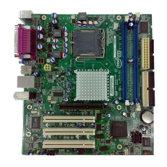
Desktop Board Features Desktop Board Components Figure 1 shows the approximate location of the major components on Desktop Board D865GSA. RJ45 Line In GMCH ICH5 Channel A, DIMM 0 Channel B, DIMM 0 OM19170 Figure 1. Desktop Board D865GSA Components... -
Page 12: Desktop Board D865Gsa Components
Intel Desktop Board D865GSA Product Guide Table 2. Desktop Board D865GSA Components Label Description Front panel audio header PCI bus connector 3 PCI bus connector 2 PCI bus connector 1 AGP connector Rear chassis fan header (3-pin) Back panel connectors... -
Page 13: Processor
12V2 rating of 13 A continuous and 16.5 A peak current for 10 ms ATX12V (version 2.0 or greater) compliant power supply Desktop Board D865GSA supports an Intel processor in the LGA775 package. Processors are not included with the desktop board and must be purchased separately. The processor connects to the desktop board through the LGA775 socket. -
Page 14: Main Memory
Main Memory NOTE ® To be fully compliant with all applicable Intel SDRAM memory specifications, the board should be populated with DIMMs that support the Serial Presence Detect (SPD) data structure. If your memory modules do not support SPD, you will see a notification to this effect on the screen at power up. -
Page 15: Intel ® 865G Chipset
® Intel 865G Chipset The Intel 865G chipset consists of the following devices: • Intel 82865G Graphics and Memory Controller Hub (GMCH) with AHA bus • Intel 82801EB I/O Controller Hub (ICH5) with AHA bus • Firmware Hub (FWH) Related Link For more information about the Intel 865GV chipset, go to: http://developer.intel.com/design/nav/pcserver.htm... -
Page 16: Lan Subsystem
• Configurable EEPROM that contains the MAC address LAN Subsystem Software For LAN software and drivers, refer to the D865GSA link on Intel’s World Wide Web site at: http://support.intel.com/support/motherboards/desktop RJ-45 LAN Connector LEDs Two LEDs are built into the RJ-45 LAN connector located on the back panel (see Figure 2). -
Page 17: Hi-Speed Usb 2.0 Support
Desktop Board Features Hi-Speed USB 2.0 Support NOTE Computer systems that have an unshielded cable attached to a USB port might not meet FCC Class B requirements, even if no device or a low-speed USB device is attached to the cable. Use a shielded cable that meets the requirements for a full-speed USB device. -
Page 18: Bios
Intel Desktop Board D865GSA Product Guide BIOS The BIOS provides the Power-On Self-Test (POST), the BIOS Setup program, the PCI and IDE auto-configuration utilities, and the video BIOS. The BIOS is stored in the Serial Peripheral Interface (SPI) Flash or the Firmware Hub. -
Page 19: Power Management Features
Desktop Board Features Power Management Features Power management is implemented at several levels, including: • Advanced Configuration and Power Interface (ACPI) • Hardware support: ⎯ Power connectors ⎯ Fan connectors ⎯ Suspend to RAM (Instantly Available PC technology) ⎯ Wake from USB ⎯... -
Page 20: Suspend To Ram (Instantly Available Pc Technology)
Intel Desktop Board D865GSA Product Guide Suspend to RAM (Instantly Available PC Technology) CAUTION For Instantly Available PC technology, the 5 V standby line for the power supply must be capable of delivering adequate +5 V standby current. Failure to provide adequate standby current when using this feature can damage the power supply and/or effect ACPI S3 sleep state functionality. -
Page 21: Wake From Usb
For more information on standby current requirements for the desktop board, refer to the Technical Product Specification by going to the following link, finding the product, and selecting Product Documentation from the left-hand menu: http://support.intel.com/support/motherboards/desktop/ Wake from USB NOTE Wake from USB requires the use of a USB peripheral that supports wake from USB. - Page 22 Intel Desktop Board D865GSA Product Guide...
-
Page 23: Installing And Replacing Desktop Board Components
2 Installing and Replacing Desktop Board Components This chapter tells you how to: • Install the I/O shield • Install and remove the desktop board • Install and remove a processor • Install and remove memory • Install and remove an AGP card •... -
Page 24: Installation Precautions
Intel Desktop Board D865GSA Product Guide Installation Precautions When you install and test the Intel desktop board, observe all warnings and cautions in the installation instructions. To avoid injury, be careful of: • Sharp pins on connectors • Sharp pins on printed circuit assemblies •... -
Page 25: Installing The I/O Shield
Installing and Replacing Desktop Board Components Installing the I/O Shield The desktop board comes with an I/O shield. When installed in the chassis, the shield blocks radio frequency transmissions, protects internal components from dust and foreign objects, and promotes correct airflow within the chassis. Install the I/O shield before installing the desktop board in the chassis. -
Page 26: Installing And Removing The Desktop Board
Refer to your chassis manual for instructions on installing and removing the desktop board. Figure 5 shows the location of the mounting screw holes for Desktop Board D865GSA. OM19173... -
Page 27: Installing And Removing A Processor
Installing and Replacing Desktop Board Components Installing and Removing a Processor Instructions on how to install the processor on the desktop board are given below. Installing a Processor CAUTION Before installing or removing the processor, make sure the AC power has been removed by unplugging the power cord from the computer;... -
Page 28: Remove The Protective Socket Cover
Intel Desktop Board D865GSA Product Guide 4. Remove the plastic protective socket cover from the load plate (Figure 8, E). Do not discard the protective socket cover. Always replace the socket cover if the processor is removed from the socket. -
Page 29: Install The Processor
Installing and Replacing Desktop Board Components 6. Hold the processor with your thumb and index fingers oriented as shown in Figure 10. Make sure fingers align to the socket cutouts (Figure 10, F). Align notches (Figure 10, G) with the socket (Figure 10, H). -
Page 30: Installing The Processor Fan Heat Sink
Desktop Board D865GSA has an integrated processor fan heat sink retention mechanism (RM). For instructions on how to attach the processor fan heat sink to the integrated processor fan heat sink RM, refer to the boxed processor manual or the Intel World Wide Web site at: ®... -
Page 31: Installing And Removing Memory
Installing and Replacing Desktop Board Components Installing and Removing Memory NOTE To be fully compliant with all applicable Intel SDRAM memory specifications, the board requires DIMMs that support the Serial Presence Detect (SPD) data structure. You can access the PC Serial Presence Detect Specification at: http://www.intel.com/technology/memory/ddr/specs/dda18c32_64_128x72ag_a.pdf... -
Page 32: Use Ddr Dimms
Intel Desktop Board D865GSA Product Guide To make sure you have the correct DIMM, place it on the illustration of the DDR DIMM in Figure 14. All the notches should match with the DDR DIMM. DDR2 OM19176 Figure 14. Use DDR DIMMs... -
Page 33: Installing Dimms
Installing and Replacing Desktop Board Components Installing DIMMs To install a DIMM, follow these steps: 1. Observe the precautions in "Before You Begin" on page 23. 2. Turn off all peripheral devices connected to the computer. Turn off the computer and disconnect the AC power cord. -
Page 34: Removing Dimms
Intel Desktop Board D865GSA Product Guide Removing DIMMs To remove a DIMM, follow these steps: 1. Observe the precautions in "Before You Begin" on page 23. 2. Turn off all peripheral devices connected to the computer. Turn off the computer. -
Page 35: Installing An Agp Card
Installing and Replacing Desktop Board Components OM19178 Figure 16. Installing an AGP Card... -
Page 36: Removing An Agp Card
Intel Desktop Board D865GSA Product Guide Removing an AGP Card Follow these instructions to remove the AGP card from the retention mechanism: 1. Observe the precautions in "Before You Begin" on page 23. 2. Remove the screw (Figure 17, A) that secures the card’s metal bracket to the chassis back panel. -
Page 37: Connecting The Ide Cables
Observe the precautions in "Before You Begin" on page 23. • Attach the cable end with the single connector (blue) to the Intel desktop board (Figure 18, A). • Attach the cable end with the two closely spaced connectors (gray and black) to the drives (Figure 18, B). -
Page 38: Connecting The Serial Ata (Sata) Cable
Intel Desktop Board D865GSA Product Guide Connecting the Serial ATA (SATA) Cable The SATA cable (4-conductor) supports the Serial ATA protocol and connects a single drive to the desktop board. For correct cable function: 1. Observe the precautions in "Before You Begin" on page 23. -
Page 39: Connecting Internal Headers
Installing and Replacing Desktop Board Components Connecting Internal Headers Before connecting cables to the internal headers, observe the precautions in "Before You Begin" on page 23. Figure 20 shows the location of the internal headers. AUD–MIC AUD–GND AUD–MIC–BIAS AUD–VCC AUD–FPOUT–R AUD–RET–R HP–ON AUD–FPOUT–L... -
Page 40: Installing A Front Panel Audio Solution
Intel Desktop Board D865GSA Product Guide Installing a Front Panel Audio Solution Figure 20, A on page 39 shows the location of the yellow front panel audio header. Table 6 shows the pin assignments for the front panel audio header. -
Page 41: Connecting To The Usb 2.0 Header
Installing and Replacing Desktop Board Components Connecting to the USB 2.0 Header Before connecting to the USB 2.0 header, observe the precautions in "Before You Begin" on page 23. See Figure 20, C on page 39 for the location of the black USB 2.0 header. Table 8 shows the pin assignments for the USB 2.0 header. -
Page 42: Connecting Chassis Fan And Power Cables
Intel Desktop Board D865GSA Product Guide Connecting Chassis Fan and Power Cables Connecting Chassis Fan Cables Connect the chassis fan cables to the 3-pin fan headers on the desktop board. Figure 21 shows the location of the chassis fan headers. -
Page 43: Connecting Power Cables
Installing and Replacing Desktop Board Components Connecting Power Cables CAUTION Failure to use the appropriate power supply and/or not connecting the 12 V (2 x 2 pin) power connector to the desktop board may result in damage to the board or the system may not function properly. -
Page 44: Other Connectors
Intel Desktop Board D865GSA Product Guide Other Connectors Figure 23 shows the location of the other connectors on the desktop board. OM19185 Item Description PCI bus add-in card connector 3 PCI bus add-in card connector 2 PCI bus add-in card connector 1... -
Page 45: Setting The Bios Configuration Jumper
Installing and Replacing Desktop Board Components Setting the BIOS Configuration Jumper NOTE Always turn off the power and unplug the power cord from the computer before moving the jumper. Moving the jumper with the power on may result in unreliable computer operation. Figure 24 shows the location of the desktop board’s BIOS configuration jumper block. -
Page 46: Clearing Passwords
Intel Desktop Board D865GSA Product Guide The three-pin BIOS jumper block enables all board configurations to be done in the BIOS Setup program. Table 10 shows the jumper settings for the BIOS Setup program modes. Table 10. Jumper Settings for the BIOS Setup Program Modes... -
Page 47: Back Panel Connectors
Installing and Replacing Desktop Board Components Back Panel Connectors NOTE The line out connector, located on the back panel, is designed to power either headphones or amplified speakers only. Poor audio quality may occur if passive (non-amplified) speakers are connected to this output. Figure 25 shows the back panel connectors. -
Page 48: Replacing The Battery
Intel Desktop Board D865GSA Product Guide Replacing the Battery A coin-cell battery (CR2032) powers the real-time clock and CMOS memory. When the computer is not plugged into a wall socket, the battery has an estimated life of three years. When the computer is plugged in, the standby current from the power supply extends the life of the battery. - Page 49 Installing and Replacing Desktop Board Components AVVERTIMENTO Esiste il pericolo di un esplosione se la pila non viene sostituita in modo corretto. Utilizzare solo pile uguali o di tipo equivalente a quelle consigliate dal produttore. Per disfarsi delle pile usate, seguire le istruzioni del produttore.
- Page 50 Intel Desktop Board D865GSA Product Guide AWAS Risiko letupan wujud jika bateri digantikan dengan jenis yang tidak betul. Bateri sepatutnya dikitar semula jika boleh. Pelupusan bateri terpakai mestilah mematuhi peraturan alam sekitar tempatan. OSTRZEŻENIE Istnieje niebezpieczeństwo wybuchu w przypadku zastosowania niewłaściwego typu baterii. Zużyte baterie należy w miarę...
- Page 51 Installing and Replacing Desktop Board Components...
- Page 52 Intel Desktop Board D865GSA Product Guide To replace the battery, follow these steps: 1. Observe the precautions in "Before You Begin" (see page 23). 2. Turn off all peripheral devices connected to the computer. Disconnect the computer’s power cord from the AC power source (wall outlet or power adapter).
-
Page 53: Updating The Bios With The Intel Express Bios Update Utility
Updating the BIOS with the Intel Express BIOS Update Utility With the Intel Express BIOS Update utility you can update the system BIOS while in the Windows environment. The BIOS file is included in an automated update utility that combines the ®... -
Page 54: Updating The Bios
If a logo appears, press <Esc> to view the POST messages. Recovering the BIOS It is unlikely that anything will interrupt the BIOS update; however, if an interruption occurs, the BIOS could be damaged. For information about recovering the BIOS for desktop board D865GSA, go to: http://support.intel.com/support/motherboards/desktop/... -
Page 55: A Error Messages And Indicators
A Error Messages and Indicators Desktop Board D865GSA reports POST errors in two ways: • By sounding a beep code • By displaying an error message on the monitor BIOS Beep Codes The BIOS also issues a beep code (one long tone followed by two short tones) during POST if the video configuration fails (a faulty video card or no card installed) or if an external ROM module does not properly checksum to zero. - Page 56 Intel Desktop Board D865GSA Product Guide...
-
Page 57: B Regulatory Compliance
Product Ecology statements • Electromagnetic Compatibility (EMC) regulations • Product certifications Safety Regulations Desktop Board D865GSA complies with the safety regulations stated in Table 13 when correctly installed in a compatible chassis. Table 13. Safety Regulations Regulation Title UL 60950-1:2003/ Information Technology Equipment –... -
Page 58: European Union Declaration Of Conformity Statement
We, Intel Corporation, declare under our sole responsibility that the product Intel Desktop Board D865GSA is in conformity with all applicable essential requirements necessary for CE marking, following the provisions of the European Council Directive 89/336/EEC (EMC Directive) and Council Directive 73/23/EEC (Safety/Low Voltage Directive). -
Page 59: Product Ecology Statements
Como parte de su compromiso de responsabilidad medioambiental, Intel ha implantado el programa de reciclaje de productos Intel, que permite que los consumidores al detalle de los productos Intel devuelvan los productos usados en los lugares seleccionados para su correspondiente reciclado. - Page 60 Intel Desktop Board D865GSA Product Guide Français Dans le cadre de son engagement pour la protection de l'environnement, Intel a mis en œuvre le programme Intel Product Recycling Program (Programme de recyclage des produits Intel) pour permettre aux consommateurs de produits Intel de recycler les produits usés en les retournant à des adresses spécifiées.
-
Page 61: Lead-Free Desktop Board
Regulatory Compliance Türkçe Intel, çevre sorumluluğuna bağımlılığının bir parçası olarak, perakende tüketicilerin Intel markalı kullanılmış ürünlerini belirlenmiş merkezlere iade edip uygun şekilde geri dönüştürmesini amaçlayan Intel Ürünleri Geri Dönüşüm Programı’nı uygulamaya koymuştur. Bu programın ürün kapsamı, ürün iade merkezleri, nakliye talimatları, kayıtlar ve şartlar v.s dahil bütün ayrıntılarını... -
Page 62: Emc Regulations
Intel Desktop Board D865GSA Product Guide EMC Regulations Desktop Board D865GSA complies with the EMC regulations stated in Table 15 when correctly installed in a compatible chassis. Table 15. EMC Regulations Regulation Title FCC Class B Title 47 of the Code of Federal Regulations, Parts 2 and 15, Subpart B, Radio Frequency Devices. -
Page 63: Ensure Electromagnetic Compatibility (Emc) Compliance
If the power supply and other modules or peripherals, as applicable, are not Class B EMC compliant before integration, then EMC testing may be required on a representative sample of the newly completed computer. Product Certifications Board-Level Certification Markings Desktop Board D865GSA has the following product certification markings: Table 16. Product Certification Markings Description Mark UL joint US/Canada Recognized Component mark. -
Page 64: Chassis And Component Certifications
Intel Desktop Board D865GSA Product Guide Chassis and Component Certifications Ensure that the chassis and certain components; such as the power supply, peripheral drives, wiring, and cables; are components certified for the country or market where used. Agency certification marks on the product are proof of certification. Typical product certifications include: In Europe The CE marking signifies compliance with all applicable European requirements.
Need help?
Do you have a question about the D865GSA and is the answer not in the manual?
Questions and answers