Dacor RV30 Installation Instructions Manual
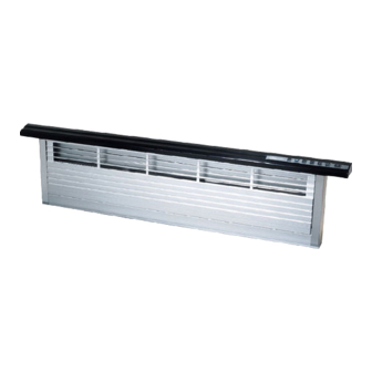
Downdraft raised vent
Hide thumbs
Also See for RV30:
- Use and care manual (12 pages) ,
- Installation instructions manual (12 pages) ,
- Planning manual (7 pages)
Table of Contents
Advertisement
Installation Instructions
Downdraft Raised Vent
Models: RV30, RV36, RV46
Includes installation instructions for optional cabinet blower (Dacor model CABP3)
Use these downdraft raised vents only with approved Dacor
cooktops.
®
See the installation instructions for the particular cooktop model being
installed to determine suitability.
Part No. 85515 Rev. H
Advertisement
Table of Contents

Related Manuals for Dacor RV30


Summary of Contents for Dacor RV30
- Page 1 Installation Instructions Downdraft Raised Vent Models: RV30, RV36, RV46 Includes installation instructions for optional cabinet blower (Dacor model CABP3) Use these downdraft raised vents only with approved Dacor cooktops. ® See the installation instructions for the particular cooktop model being installed to determine suitability.
-
Page 2: Table Of Contents
ANSI/UL 858 household electrical ranges, CAN/CSA-C22.2 NO. 64 Standard for Household Electric Cooking and Liquid Heating Appliances, and UL 507 electric fans. All specifications subject to change without notice. Dacor assumes no liability for changes to specifications. © 2007 Dacor, all rights reserved. -
Page 3: Important Safety Instructions
• Always contact the Dacor Customer Service Team about problems and conditions that you don’t under- Hazards or unsafe practices that COULD result in severe stand. See Customer Service Information on page 2. -
Page 4: General Safety Precautions
Do not allow foreign objects, • Install or locate this appliance only in accordance such as cigarettes or napkins, to be sucked into the with these installation instructions the Dacor cooktop vent holes. installation instructions and the remote or in-line •... -
Page 5: Product Specifications
Adjustable anchor legs Front View Model A - Top Cap B - Chassis Number width width RV30 30” (762 mm) 27 3/8” (695 mm) RV36 36” (914 mm) 33 3/8” (848 mm) RV46 46” (1168 mm) 43 3/8” (1102 mm) -
Page 6: Installation Specifications
The vent system consists of the raised vent itself and a sin- The electric service for the raised vent should be installed gle, Dacor approved, externally mounted blower (see page only by a licensed electrician. 5 and 6 for examples). - Page 7 Installation Specifications • The raised vent exhaust may be configured to vent Raised vent with through the bottom or through one of the sides. Allow cabinet blower ° elbow room for the exhaust duct coming out of the unit. mounted to front See Planning the Duct Work (page 7) for additional details.
- Page 8 Installation Specifications General System Layout (Continued) Cabinet back Outside wall Raised vent Cooktop Raised vent configured for bottom exhaust Wall cap on outside wall 3 1/4” X 10” to round transition Floor Duct work Duct work Wiring/conduit from raised vent ILHSF series to in-line blower in-line blower...
-
Page 9: Planning The Duct Work
• You can increase the duct size over the duct run if You must install one of the Dacor blower models listed desired. To prevent a back draft, never decrease the below for proper operation. For ILHSF or REMP series duct size over the run. - Page 10 Bottom exhaust configutation Front Exhaust Dimensions with rear or bottom duct routing CABP3 Blower - Left Exhaust DUCT Model RV30 2” (51 mm) 6” (152 mm) 12” (205 mm) RV36 Exhaust Locations and Side Dimensions RV46 5” (127 mm) 9” (229 mm) 9”...
- Page 11 Installation Specifications Calculating the Maximum Duct Run Length Equivalent Number of Feet - Duct Elbows and Transitions • Do not use duct work that is smaller in cross-sectional 45° elbow 3 ¼” X 10 area than the required duct sizes in the table to the 3 feet 7 feet 8 Inch...
-
Page 12: Installation Instructions
Installation Instructions Parts List Locate the 3 ¼” X 10 duct mounting flange included with the unit. Attach it to the open exhaust hole using the two (2) screws removed in step 1, with the flange • Product literature facing outward. •... -
Page 13: Installing The Vent In The Cutout
Installation Instructions Installing the Vent in the Cutout ILHSF or REMP Series Blower Installation If using a ILHSF or REMP series blower, install it according NOTE: The raised vent installs in the back of the cutout, to the blower installation instructions. separate from the cooktop. -
Page 14: Electrical Installation
Installation Instructions Duct Work Installation On installations using an cabinet blower (CABP3): • Remove the electrical access cover from the front • Install the duct work from the raised vent to the point of the blower. where it exits the building according to the Installation Specifications. - Page 15 Installation Instructions Raised vent electrical connections - REMP series see Wiring Diagram B blower shown Connect wires/conduit Cabinet blower according to remote or in-line Junction (CABP3) blower installation instructions Blower electrical connections Power supply wiring from Raised vent - see Wiring Diagram A junction to raised vent electrical connections -...
-
Page 16: Final Installation
Dacor Distinctive Service at (877) 337-3226. Have the model and serial numbers from the product data labels for the raised vent and the blower available when you call. Dacor is not responsible for the cost of correcting problems caused by a faulty installation. -
Page 17: Technical Data
Technical Data RV Raised Vent Wiring Diagram TO PUSH BUTTON CIRCUIT LOWER UPPER BOARD LIMIT SWITCH LIMIT SWITCH POWER CONTROL CIRCUIT BOARD GRN/YEL CHASSIS GROUND STUD GND GND BLOWER POWER GROUND OUTPUT INPUT CABP3 Cabinet Blower Ratings CABP3 Blower Performance CABP3 Cabinet blower Airflow* Nominal 600 CFM... - Page 18 Notes...
- Page 20 Dacor ● 600 Anton Blvd. Suite 1000 Costa Mesa, CA 92626 ● Phone: (800) 793-0093 ● Fax: (626) 403-3130 ● www.Dacor.com...
Need help?
Do you have a question about the RV30 and is the answer not in the manual?
Questions and answers
How to replace filters on Dacor RV30
To replace filters on the Dacor RV30:
1. Turn off power to the vent system.
2. Locate the grease filter inside the vent hood.
3. Remove the old grease filter by sliding or pulling it out, depending on the model.
4. Insert the new grease filter (model RV30) in the same position.
5. Ensure it is securely in place.
6. Restore power and test the system.
Use only approved Dacor grease filters for proper fit and function.
This answer is automatically generated