Table of Contents
Advertisement
Quick Links
Download this manual
See also:
User Manual
Part No. 109408 Rev. A
Renaissance
®
Models RNIVS1, RNIVS2, RNIVSR1, and RNIVSR2
APPROVED FOR USE WITH ALL DACOR
TESTED IN ACCORDANCE WITH THE LATEST EDITION OF ANSI/UL 507
STANDARD FOR ELECTRIC FANS AND CAN/CSA-C22.2 NO. 115 STANDARD
FOR FANS AND VENTILATORS.
Integrated Ventilation Systems
®
Installation Instructions
RANGES AND COOKTOPS.
Advertisement
Table of Contents

Related Manuals for Dacor Renaissance RNIVS2


Summary of Contents for Dacor Renaissance RNIVS2
- Page 1 Integrated Ventilation Systems ® Models RNIVS1, RNIVS2, RNIVSR1, and RNIVSR2 ® APPROVED FOR USE WITH ALL DACOR RANGES AND COOKTOPS. TESTED IN ACCORDANCE WITH THE LATEST EDITION OF ANSI/UL 507 STANDARD FOR ELECTRIC FANS AND CAN/CSA-C22.2 NO. 115 STANDARD FOR FANS AND VENTILATORS.
-
Page 2: Table Of Contents
RNIVS, above the filters on the back wall of the chassis. Remove the filters to locate the plate. All specifications subject to change without notice. Dacor assumes no liability for changes to specifications. © 2008 Dacor, all rights reserved. -
Page 3: Important Information About Safety Instructions
Immediate hazards that WILL result in severe personal • Always contact the Dacor Customer Service Team injury or death. about problems and conditions that you don’t under- stand. -
Page 4: General Safety Precautions
Important Safety Instructions General Safety Precautions To reduce the risk of fire, electric shock, serious injury or death when using your appliance, follow basic safety precautions, including the following: CAUTION For general ventilating use only. Do not use to exhaust hazardous or explosive materials and vapors. WARNING WARNING –... - Page 5 The user should not install, repair, or replace any part of the unit unless specifically recommended in the literature accompanying it. A qualified service technician should perform all other service. Contact the nearest Dacor autho- rized service representative at (800) 793-0093, or at www.dacor.com for examination, repair or adjustment.
-
Page 6: Product Specifications
* Electrical specifications are provided for reference only. Consult the product data label on the unit for exact specifi- cations. ** Rated at zero-inches static pressure. Dacor Blower Models Used in RNIVSR Series: RNIVSR models do not have blowers. Blowers must be purchased separately. In-Line Style... -
Page 7: Dimensions
Product Specifications Product Dimensions All tolerances are +1/16”, -0” (+0.16, -0 cm) RNIVS1 & RNIVSR1 ISO View 8 7/ 8” (22.5 cm) 3/ 8” (1.0 cm) 3/8” Rear Flange Extension 20 1/ 4” 18 1/ 2” (54.43 cm) (46.92 cm) 21 7/ 16”... - Page 8 Product Specifications Product Dimensions All tolerances are +1/16”, -0” (+0.16, -0 cm) RNIVS1 & RNIVSR1 Rear View 3/ 8” back panel (1.0 cm) channel height 2 1/ 8” (5.04 cm) Channel Dimensions Side View 3/ 8” (1.0 cm) flange channel depth 3/ 8”...
- Page 9 Product Specifications Product Dimensions All tolerances are +1/16”, -0” (+0.16, -0 cm) RNIVS2 & ISO View RNIVSR2 8 7/ 8” (22.5 cm) 3/ 8” 3/8” Rear Flange (1.0 cm) Extension 30 1/ 4” (76.84 cm) 19 5/ 8” 18 1/ 2” (49.82 cm) 31 7/16 ”...
- Page 10 Product Specifications Product Dimensions All tolerances are +1/16”, -0” (+0.16, -0 cm) RNIVS2 & Rear View RNIVSR2 3/ 8” back panel (1.0 cm) channel height 2 1/ 8” (5.04 cm) Channel Dimensions Side View flange 3/ 8” (1.0 cm) 3/ 8” 3/8”...
-
Page 11: Preparation And Setup
Baffle filter and hardware (2) Dimmable LED light bulbs (2) Light replacement tool (1) Literature (2) Dacor Stainless Cleaning Creme (1) Necessary Tools and Hardware Optional Accessories Please make sure these tools and hardware are within The items below are optional accessories that can be reach before beginning the installation. -
Page 12: Meeting Installation Requirements
An RNIVS installed inside any custom hood canopy Combustible Materials (wood) 36 inches (91.5 cm) using a Dacor RNIHL Series Stainless Steel Hood Non-Combustible (tile, metal) 30 inches (76.2 cm) Liner must be a minimum of 30” (76.2 cm) above the countertop cooking surface. -
Page 13: Meeting Electrical Codes
Preparation and Setup Meeting Electrical Codes WARNING Make sure electrical service to the RNIVS is installed by a licensed electrician. It is the owner’s responsibility to confirm that all electrical requirements are met by a qualified electrician who is servicing this appliance. The electrical installation, including the minimum supply- wire size and grounding, must be in accordance with the National Electric code ANSI/NFPA* (or latest revision), local... -
Page 14: Planning The Ductwork
If multiple elbows are used, try to keep at least 24 inches of • On dual exhaust models, the two 8-inch exhausts may straight duct between each elbow. be merged into one 10-inch duct using Dacor transition kit ATD10. See page 12 for details. Avoid using “S” or back-to-back adjacent elbows. •... -
Page 15: Installation Instructions
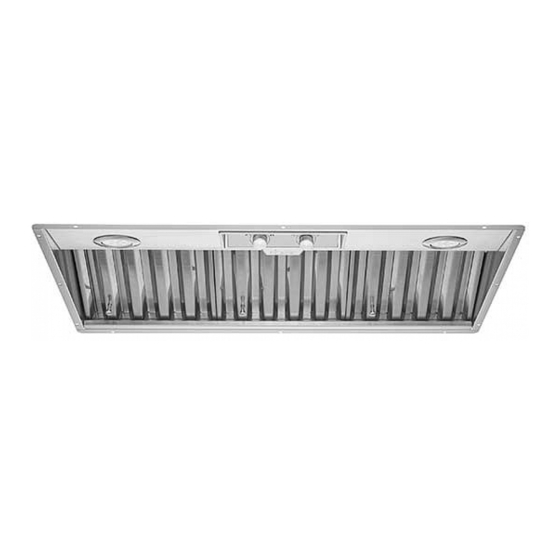
Installation Instructions Assembling the Filters Filters are boxed separately and must be assembled during installation. All knobs and hardware are included with the filters. To ensure the correct orientation, make sure the top of the filter lays face-up. The face of the filter has: •... -
Page 16: Installing The Hood Liner Kit Rnihl
Installation Instructions Installing the Hood Liner Kit #RNIHL The Renaissance ® series (RN) Integrated Hood Liner (RNIHL) is available separately and must be installed before the RNIVS. Hood Canopy The RNIHL liners are made from of durable, non- combustible stainless steel. The latest Renaissance ® design make it an excellent component for any custom hood. -
Page 17: Attaching The Dual To Single Transition Kit Atd10
Attaching the Dual to Single Transition Kit #ATD10 Two 8-inch duct exhausts can be transitioned into one 10 inch round 10-inch duct. • Attach the Dacor transition kit # ATD10 before installing the RNIVS. 2" (5.1 cm) • This transition kit fits over the top ventilation exits. -
Page 18: Marking The Centerlines
Installation Instructions Marking the Centerlines 10 23/ 32” 10 23/ 32” (27.69 cm) (27.69 cm) These measurements and marks are for centering the RNIVS and marking the duct cutouts. Have a marking tool and tape measure ready. 6 3/ 16” 1. -
Page 19: Installing The Rnivs
Installation Instructions Installing the RNIVS WARNING Installing the RNIVS requires two people. Do not attempt to lift and hold the RNIVS without assistance. Wear protective gloves while holding the unit. Sharp edges can cause injury to hands and fingers. NOTE: If using the RNIVS without a liner kit, use NOTE: If using a liner kit with the RNIVS, please a 3/8”... - Page 20 Installation Instructions Adding a Spacer If using the RNIVS without a liner kit, use a 3/8” spacer: 3/ 8” The flange circling the bottom of the unit will not (1.0 cm) allow the unit to lay flat against a wall. depth Therefore, use a 3/8”...
-
Page 21: Hardwiring The Hood
Installation Instructions Hardwiring the Hood WARNING remote blower series: REMP or ILHSF wiring terminal inside unit • To avoid electric shock or fire hazard, make sure that power to the RNIVS power supply line is turned OFF at the fuse box or circuit breaker before connecting Not used the electrical wiring. - Page 22 Installation Instructions Grounding to a Cold Water Pipe WARNING Meter • Do not ground the circuit to a gas line. No. 4 copper • Do not ground the circuit to a hot water pipe. wire • Water lines that are insulated must be jumped to assure continuity to ground.
- Page 23 Installation Instructions Inserting Dimmable Light Bulbs Size: PAR16, E26/27 75 Watt max., 60 Amp Make sure dimmable bulbs are used. The electronic board is designed for dimmable light bulbs and using non-dimma- ble types will cause damage and faulty performance. Shut the main circuit breaker OFF while inserting new bulbs or while changing bulbs.
-
Page 24: Verifying The Setup
4. Repeat the above steps. Dimmable LED Bulb Kit 702666 (1 Bulb + Suction Cup) • If the RNIVS still does not work, contact Dacor Distinctive Service at (800) 793-0093 ex. 2822. Halogen Bulb Kit 700975 (1 Bulb + 1 Suction Cup) •... -
Page 25: The Installation Checklist
• Proper installation is the responsibility of the home- owner. The importance of proper installation of your Dacor range RNIVS cannot be overemphasized. □ Is the RNIVS properly attached to the canopy accord- ing to the instructions on pages 18? □... -
Page 26: Wire Diagrams
REMOTE BLOWER ONLY LIGHT LAMP LIGHT DIMMER CONNECTION TO ARLC/ARSC /ARSLC SWITCH FAN MOTOR CONNECTION TO REMOTE BLOWER P/N: ILHSF -8/10 OR REMP -3/16 DISCONNECT POWER SUPPLY AT THE DACOR P/N: FUSE BOX BEFORE SERVICING THIS EQUIPMENT. 109392 REV A... - Page 27 LIGHT LAMP LIGHT DIMMER CONNECTION TO ARLC/ARSC /ARSLC SWITCH FAN MOTOR FAN MOTOR CONNECTION TO REMOTE BLOWER P/N: ILHSF -8/10 OR REMP -3/16 CAUTION: DISCONNECT POWER SUPPLY AT THE DACOR P/N: FUSE BOX BEFORE SERVICING THIS EQUIPMENT. 109391 REV A...
- Page 28 Dacor ● 14425 Clark Avenue, City of Industry, CA 91745 ● Phone: (800) 793-0093 ● Fax: (626) 403-3130 ● www.dacor.com...
Need help?
Do you have a question about the Renaissance RNIVS2 and is the answer not in the manual?
Questions and answers