Table of Contents
Advertisement
Quick Links
Advertisement
Table of Contents

Subscribe to Our Youtube Channel
Related Manuals for Directed Audio 1200T


Summary of Contents for Directed Audio 1200T
- Page 1 1200 t model...
-
Page 2: Table Of Contents
Featuring high-efficiency MOSFET power supplies, flexible on-board crossovers, and state of the art audio design, Directed Audio power amplifiers will excite and delight the mobile sound TABLE OF CONTENTS Congratulations .........2 Limited Two-year Consumer Warranty . -
Page 3: Limited Two-Year Consumer Warranty
LIMITED TWO-YEAR CONSUMER WARRANTY Directed Electronics, Inc. promises to the original purchaser, to replace this product should it prove to be defective in workman- ship or material under normal use, for a period of two years from the date of purchase by the dealer as indicated by the date code marking of the product PROVIDED the product was installed by an authorized... -
Page 4: Warning
FEATURES High-speed MOSFET switching power supply and dual N-channel MOSFET outputs Stereo, mono, or simultaneous stereo/mono operation Thermal, DC offset, reverse polarity, short circuit and over/under voltage protection Top-mounted controls located under smoked plexiglass cover Programmable features controlled via ESP serial databus and Directed's proprietary Bitwriter ®... -
Page 5: Note
NOTE Prior to servicing your vehicle ensure that the alarm system is d d i i s s a a r r m m e e d d . Due to the amplifier’s anti-theft feature (if enabled), if the main power to the INSTALLATION GUIDELINES 1. - Page 6 cable of the vehicle, and if neces- sary, upgrade it by adding an addi- tional ground wire that is the same gauge as the amplifier's power wire. Remember, the amplifier can only deliver its rated output when it is not current limited by the power and ground supply wires.
-
Page 7: Front Panel Connections/Status Led
3. S S p p e e a a k k e e r r L L o o a a d d S S e e l l e e c c t t - Set 1 or 2/4 ohm to match the stereo load impedance of the system. 4. F F a a n n P P o o r r t t - connection port for FIGURE 1—AMPLIFIER CONNECTIONS 1200T FRONT SPEAKER LOAD OUTPUT INPUT SELECT ©... -
Page 8: Rear Panel Connections
REAR PANEL CONNECTIONS 1. S S p p e e a a k k e e r r O O u u t t T T e e r r m m i i n n a a l l s s - Connect the speakers to these terminals. -
Page 9: Top Panel Features
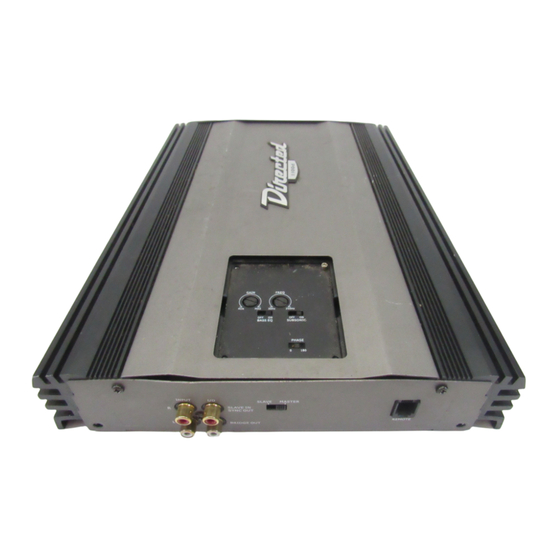
FIGURE 2—AMPLIFIER CONNECTIONS 1200T REAR 2, 3 1 MIN FUSE 30A x 3 POWER BRIDGED ONE OHM TOP PANEL FEATURES Control Panel Cover The gain and filter controls are located under a control panel cover on top of the amplifier. The control panel cover must be removed to gain access to the gain and filter controls. -
Page 10: Amplifier Controls Top
AMPLIFIER CONTROLS TOP 1. E E S S P P P P o o r r t t - - Allows programming of the amplifier using the Bitwriter ® 2. S S u u b b s s o o n n i i c c F F r r e e q q u u e e n n c c y y H H z z - - This control adjusts the subsonic filter cutoff (between 15-50 Hz). - Page 11 FIGURE 3—AMPLIFIER CONTROLS TOP PORT XOVER FREQ Hz XOVER SLOPE 12 24 BASS GAIN BOOST MODE MONO STEREO N N O O T T E E : : The adjustment for Gain is a digital control (potentiometer). Although it will have the feel of adjustment like the other controls on this panel (there are no detents), the Gain control has 33 discrete steps in adjustment.
-
Page 12: Esp Features And Controls
ESP FEATURES AND CONTROLS The ability to access the feature settings of your amplifier is only possible with the use of a Directed Electronics Bitwriter unit. Firmware version 1.8 or ® later is required in the Bitwriter ® Versions prior to 1.8 will not program the amplifier. -
Page 13: Speaker Wiring Diagrams
SPEAKER WIRING DIAGRAMS Stereo operation (top view) Mono operation (top view) Simultaneous stereo/mono operation (top view) 1 1 3 3 © 2004 Directed Electronics, Inc... -
Page 14: Crossover Settings And Gain Adjustment
N N o o t t e e : : Remember that the 1200t uses a digital gain control with a finite number of adjustment steps. A very small adjustment may not cause any audible change in level. -
Page 15: Subsonic Filter Adjustment
SUBSONIC FILTER ADJUSTMENT This amplifier incorporates a subsonic filter to maximize the performance of a subwoofer. The subsonic filter is a high pass filter that removes unwanted bass output at very low frequencies from the woofer. This increases the output of a subwoofer by as much as 3 dB by increasing the mechan- ical power handling of the subwoofer. -
Page 16: Specifications
SPECIFICATIONS Power Output: 200 Watts RMS X 2 Channels at 4 Ohms and < 1% THD+N Signal to Noise Ratio: 80 dBA (reference 1 Watt into 4 Ohms) RMS continuous power per channel, driven in 4 ohm mode @ 14.4 VDC RMS continuous power per channel, driven in 1 ohm mode @ 14.4 VDC Conversion Efficiency... - Page 17 RCA Input/Output Jacks Input Impedance Input Sensitivity Supply Voltage Fusing and Power Minimum Cable Requirements (AWG) Dimensions Port Output (Optional Fan) © 2004 Directed Electronics, Inc 2-channel in/2-channel buffered full-range out 30K ohms Variable from 250 mV to 8 volts 10 to 16 VDC 30A (qty 3) 19 x 9¾...
- Page 18 Directed Electronics, Inc. Vista, California 92081 www.directed.com Directed is a proud member of Quality Directed products are sold and serviced throughout North America and around the world Call 800 274 0200 for more information about our products and services © 2004 Directed Electronics, Inc. - All rights reserved - G45027 10/04 The company behind this system is Directed Electronics, Inc.
Need help?
Do you have a question about the 1200T and is the answer not in the manual?
Questions and answers