Sign In
Upload
Manuals
Brands
DH Instruments Manuals
Controller
PPCH - V1.01
DH Instruments PPCH - V1.01 Manuals
Manuals and User Guides for DH Instruments PPCH - V1.01. We have
1
DH Instruments PPCH - V1.01 manual available for free PDF download: Operation And Maintenance Manual
DH Instruments PPCH - V1.01 Operation And Maintenance Manual (192 pages)
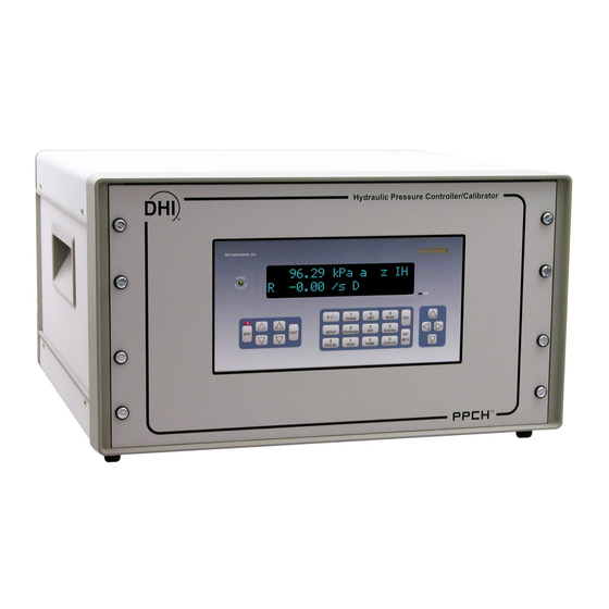
Hydraulic Pressure Controller/Calibrator Ver. 1.01f and higher
Brand:
DH Instruments
| Category:
Controller
| Size: 5 MB
Table of Contents
Table of Contents
3
Table of Contents
5
Tables
7
A B O U T T H I S M a N U al
9
1 Introduction
11
I N T R O D U C T I on
11
Product Overview
11
Specifications
12
General Specifications
12
Pressure Measurement Specifications
13
Quartz Reference Pressure Transducer (Q-Rpt)
13
Table 1. Reference Pressure Transducer (Q-RPT) Designations and Ranges
13
Utility Sensor
14
On-Board Barometer
14
Pressure Control Specifications
14
2 Installation
15
Unpacking and Inspection
15
Removing from Packaging
15
Inspecting Contents
15
Table 2. PPCH Packing List
15
Site Requirements
16
Installation in a 19 In. Rack Mount
16
Initial Setup
17
Preparing for Operation
17
Front and Rear Panels
17
Front Panel
17
Figure 1. Front Panel
17
Rear Panel
18
Power Connection
18
Remote [Enter/Set P] Connection (Footswitch or Other Switch)
18
Figure 2. Rear Panel
18
Connecting Pneumatic Power (Drive Port)
19
Setting up and Filling the Fluid Reservoir
19
Internal Reservoir
19
Table 3. Drive Air Requirements
19
External Reservoir
21
Figure 3. Internal Reservoir Setup
21
Reservoir Return Settings
22
Figure 4. External Reservoir Setup
22
Installing Pump Drive out Gas Exhaust Filter
23
Table 4. Reservoir Return Settings for Internal or External Reservoir
23
Figure 5. Installing the Exhaust Filter/Muffler
23
Connecting to Other Devices
24
Installing a Line Filter to Protect the Ppch
24
Connecting to an Rpm4 to be Used as an External Reference Device
24
Connecting to a Pg7302 Piston Gauge
26
Figure 6. Connecting PPCH to an RPM4 or PG7302 Using the Standard
26
PPCH Interconnection Accessories
26
Connecting to a Device under Test (Test Port)
27
Check/Set Security Level
27
Turn off Absolute Measurement Mode
28
Power-Up and Verification
28
Switch Power on
28
Apply Pneumatic Power (Drive Air)
28
Check Pressure Measurement Operation
28
Checking Absolute Mode Pressure Measurement
28
Checking Gauge Mode Pressure Measurement
29
Prime and Purge Test System
29
Leak Check
29
Check Pressure Control Operation
29
Storage and Shipping
30
Short Term Storage
30
Long Term Storage
30
Preparation for Shipping
30
3 O P E R a T I O
31
User Interface
31
Main Run Screen
31
Table 5. MAIN RUN Screen Display Fields
32
Function / Data Keypad Layout and Protocol
33
Figure 7. Keypad Layout
33
Direct Pressure Control Keys
34
Figure 8. Direct Pressure Control Keys
34
Remote [Ent/Set P] (Foot)Switch
35
Sounds
35
General Operating Principles
35
Pressure Control Principles
35
Figure 9. Pressure Control System Schematic
37
Automated Pressure Control
38
Idle, no Automated Control (Measure Mode)
38
Dynamic Control
39
Figure 10. Dynamic Pressure Control Operation
39
Static Control
40
Figure 11. Ready/Not Ready in Dynamic Pressure Control Mode
40
Figure 12. Static Pressure Control Operation
40
Monotonic Control
41
Figure 13. Ready/Not Ready in Static Control Mode
41
Ramp Control
42
Figure 14. Monotonic Pressure Control Operation
42
Figure 15. Ready/Not Ready in Monotonic Pressure Control Mode
42
Figure 16. Ramp Pressure Control Operation
43
Figure 17. Ready/Not Ready in Ramp Pressure Control Mode
43
Pressure Ready/Not Ready
44
Gauge Measurement Mode, Dynamic Compensation for Atmospheric Pressure
44
Multiple Internal and External Q-Rpts
45
Multipe Ranges (Q-Rpts, Autorange and Infinite Ranging)
46
Table 6. Position Designators of Q-Rpts in a PPCH System
46
Fluid Reservoir Low Level Warning
47
Table 7. Settings and to What They Are Specific (Range, Measurement Mode, Q-RPT, System)
47
Operation with a Pg7000 Piston Gauge
48
Direct Function Keys Summary
48
Table 8. Summary of PPCH Function Key Operation
48
Direct Function Keys
49
Range]
49
Unit]
50
Mode]
51
Autorange]
52
Table 9. Settings Made by Autorange
53
Rpt]
54
Autotest]
56
Quick Autotest
57
Qdut Autotest
59
Head]
62
Prime]
64
1Prime
65
2Purge
66
Leak Ck]
66
Ent/Set P] (Set Pressure Automatically)
68
Dynamic Control Mode, [Ent/Set P]
68
Static Control Mode, [Ent/Set P]
69
Monotonic Control Mode, [Ent/Set P]
71
Ramp Control Mode, [Ent/Set P]
72
Interrupting Automated Pressure Control
73
Automated Pressure Commands for Zero Pressure
73
Setup]
74
1Range
74
Saving an Autorange Range
74
Deleting Autorange Ranges
75
2Res> (Resolution)
75
3Jog
76
4Ul> (Upper Limit)
77
Over Pressure Function
78
5Atest
78
6Control
79
1Limits> (Custom Control Parameters)
80
Table 10. Default Pressure Control Parameters
80
2Mode
82
Turning-Off Custom Control Parameters
83
7Drv> (Drivers)
83
Special]
84
1Autoz
84
Table 11. Autoz on and off
86
Edit Autoz
87
Run Autoz
88
2Remote
89
1Com1, 2Com2
90
3Ieee-488
90
4Format
90
5Rs232 Self-Test
91
3Head
91
4Reset
92
1Sets
92
2Units
93
3Atest
93
4Cal
93
Table 12. Reset - Sets
93
5All
94
5Pref
94
Table 13. Reset - Cal
94
Table 14. Reset - All
94
1Scrsvr
95
2Sound
95
3Time
96
4Id
96
5Level> (Security)
97
Table 15. Security Levels
98
6Punit
99
Table 16. UNIT Function - Available Units of Measure
100
7Internal
101
1Config
101
2Baro
101
3Pump
102
8Cal
104
9Log
104
4 Remote Operation
107
Overview
107
Interfacing
107
Rs232 Interface
107
Com1
107
Table 17. COM1 Pin Designations and Connections
107
Ieee-488
108
Com2
108
Programming Formats
108
Table 18. COM2 DB-9F Pin Designations
108
Classic Program Message Format
109
Enhanced Program Message Format
109
Using Command Type Commands
109
Using Query Type Commands
110
Commands
111
Programming Messages
111
Table 19. Program Message List
111
Error Messages
112
Table 20. Error Numbers (#) and Descriptions
112
Program Message Description Overview
113
Program Message Descriptions
114
Status Reporting System
138
Error Queue
138
Status Byte Register
138
Table 21. 8 Bit Status Byte Register
138
Figure 18. Status Register Schematic
139
Standard Event Register
140
Ready Status Register
140
Table 22. 8 Bit Standard Event Register
140
Table 23. 8 Bit Ready Status Register
140
Ieee Std. 488.2 Common and Status Program Messages
141
Program Message Descriptions
141
Table 24. Program Message List
141
5 Maintenance, Adjustments a N D C a L I B R a T I O
145
Overview
145
Preventive Maintenance
145
Table 25. PPCH Maintenance Parts
146
Calibration of Quartz Reference Pressure Transducers (Q-Rpts)
147
Principle
147
Pa and Pm Coefficients
147
As Received and as Left Data
148
Equipment Required
149
Set up and Preparation
149
Recommended Calibration Point Sequence
149
Turning off Absolute Measurement Mode for a Q-Rpt
150
Table 26. Calibration Point Sequence, Standard Class, Q-Rpts
150
Q-Rpt Calibration Using Caltool for Rpts Software
151
Editing and Viewing Q-Rpt Calibration Information
151
Q-Rpt Calibration/Adjustment Without Caltool for Rpts Software
153
Adjustment of On-Board Barometer
154
Adjustment of Utility Sensor
154
Filling and Draining the Fluid Reservoir
155
Internal Reservoir
155
Filling the Internal Reservoir
155
Draining the Internal Reservoir
156
External Reservoir
156
Filling the External Reservoir
156
Figure 19. Internal Reservoir Schematic
156
Draining the External Reservoir
157
Figure 20. External Reservoir Schematic
157
Purging Contaminated Fluid from the Ppch
158
Volume Configuration
158
Valve Opening Point Configuration
160
Accessing Ppch Mechanical Module
161
Hydropneumatic Pump
162
Priming the Pump
162
Priming the Pump Check Valve
163
Pump Replacement
164
Pump Spool Valve Inspection or Repair
166
Pump Inlet Filter (Liquid) Replacement
168
Leak Checking
169
Pressure Decay Leak Testing Method
169
Localizing a Leak Within the Ppch
170
High Pressure Vent Valve Leak
171
Low Pressure Isolation Valve Leak
173
Low Pressure Vent Valve Leak
173
Valve Replacement or Repair
175
Shutoff Valve Replacement
175
Control Valve Service
176
Reloading Embedded Software into Flash Memory
176
Subassembly Description and Location
177
Electronic Module
177
Power Entry and Fuse
177
Power Supplies
177
Figure 21. Electronic Module, Internal View
177
Driver Board
178
Mini Micro Board
178
On-Board Barometer
178
Mechanical Module
179
Pump Drive Air Pressure Transducer
179
Hi Q-Rpt or Utility Sensor
179
Figure 22. Mechanical Module, Internal View
179
Test Vent Valve
180
Lo Q-Rpt Shutoff Valve
180
Lo Q-Rpt
180
Lo Q-Rpt Vent Valve
180
Pump Accumulator
180
Front Panel
180
Electrical Cable Track
180
5.14.2.10 Hydropneumatic Pump
180
5.14.2.11 Inlet Control Valve
180
5.14.2.12 Outlet Control Valve
181
5.14.2.13 Fluid Reservoir
181
Reservoir Overflow/External Reservoir Return Tube
181
Thermal Pressure Control Unit (Tpcu)
181
5.14.2.16 Drive Pressure Regulator
181
Table 27. Troubleshooting Guide
183
7. Appendix
187
7 Appendix
187
Drivers
187
Table 28. External Drivers Current Output
187
Table 29. External Drivers Pin Outs
187
Figure 23. Drivers Connector Schematic
187
Unit Conversion
188
Pressure
188
Remote [Ent]
188
Table 30. Pressure Unit of Measure Conversion Coefficients
188
Figure 24. Remote [ENT/SET P] Connector Schematic
188
8 Warranty
189
Overview
189
Table 31. DHI Authorized Service Providers
189
Advertisement
Advertisement
Related Products
DH Instruments VLPC
DH Instruments PPCH
DH Instruments VLI
DH Instruments PPCH-G
DH Instruments FPG8601
DH Instruments GPC1-10000
DH Instruments GPC1-10000-AF
DH Instruments GPC1-16000
DH Instruments MPC1-1000
DH Instruments Categories
Controller
Measuring Instruments
Racks & Stands
Cables and connectors
Accessories
More DH Instruments Manuals
Login
Sign In
OR
Sign in with Facebook
Sign in with Google
Upload manual
Upload from disk
Upload from URL