Sign In
Upload
Manuals
Brands
DH Instruments Manuals
Controller
FPG8601
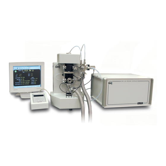
DH Instruments FPG8601 Manuals
Manuals and User Guides for DH Instruments FPG8601. We have
1
DH Instruments FPG8601 manual available for free PDF download: Operation And Maintenance Manual
DH Instruments FPG8601 Operation And Maintenance Manual (166 pages)
Brand:
DH Instruments
| Category:
Controller
| Size: 3 MB
Table of Contents
Table of Contents
3
A B O U T T H I S M a N U al
11
1 I N T R O D U C T I on
13
Overview
13
2 . W a R R a N T y S T a T E M E N
13
Requirements
14
Specifications
14
General Specifications
14
Fpg8601 General Specifications
14
Ambient and Instrument Condition Measurements
15
Piston-Cylinder
15
Pressure Measurement
15
Vlpc General Specifications
16
Fpg Platform Front and Rear Panels and Vlpc Front and Rear Panels
17
Terminal Front and Rear Panels
17
Fpg Terminal Front Panel
17
10 . T R O U B L E S H O O T I N
17
Figure 1. FPG8601 Terminal Front Panel
17
Fpg Terminal Rear Panel
18
Figure 2. FPG8601 Terminal Rear Panel
18
Fpg Platform Front View
19
1 . a P P E N D I
19
Figure 3. FPG Platform Front View
19
Fpg Platform Back View
20
Figure 4. FPG Platform Back View
20
Vlpc Rear Panel Assembly
21
Figure 5. VLPC Rear Panel
21
7 P I S T O N - C y L I N D E R M a I N T E N a N C
19
2 F P G T H E O R y O F O P E R a T I O
23
Overview
23
Piston-Cylinder
23
Figure 6. Piston-Cylinder Lubricating Flow
24
Load Cell
25
Figure 7. Internal Calibration Mass Alignment
25
Lubrication Pressure
26
Vacuum Reference Pressure
26
Simplified Formula for Calculating Differential Pressure
27
Reference Level
28
Corrections
28
Δn1
28
Δn2
28
Δn3
29
Figure 8. FPG Forces
29
Complete Differential Pressure Equation
30
50 L P C T H E O R y O F O P E R a T I O
31
Overview
31
Table 1. Nominal VLPC Ranges
31
Supply and Regulation
32
Flow Control
32
Figure 9. Gauge Mode VLPC Block Diagram
32
Figure 10. Absolute Mode VLPC Block Diagram
32
Range Restrictions
33
Control
33
Table 2. Nominal VLPC Ranges, 15 Kpa Unit
33
Ready/Not Ready
34
Figure 11. VLPC Ready Criterion
34
4 G E T T I N G S T a R te
35
Overview
35
Installing Fpg Tools
35
Figure 12. FPG8601 System Schematic
35
Setting up Fpg Tools
36
Basic Fpg Hardware Setup
37
Table 3. Equipment for Basic FPG Hardware Setup
37
Setting up the Piston-Cylinder
38
Connecting the Fpg Manifold and Valves
38
Figure 13. FPG8601 Manifold Connection
39
Setting up the Fpg for Operation
40
Setting up the Vlpc
41
Introducing Gas to the Fpg
41
Connecting a Dut
42
Gauge Mode
42
Absolute Mode
42
Absolute Differential Mode
43
Connecting the Dut Manifold
44
Setting up the Turbo Pump
45
Connecting the Ion Gauge
45
Changing Lubrication Gas
46
Purging the Lubricating Volume with a New Gas
46
Purging the Test Port
47
5 S y S T E M O P E R a T I O
49
Overview
49
Zeroing the Fpg
49
Zero Condition
49
Stability Test
50
Store Zero Data
50
Internal Calibration
50
Determining Calibration Mass Value
50
Activating New Calibration
51
Figure 14. Internal Calibration Results Window
51
Table 4. Internal Calibration Results Options
52
Setting a Measurement Mode
53
Using a Dut with Fpg Tools
53
Zeroing the Dut Manifold
54
Changing Pressure with the Vlpc
54
Setting 0 Pressure
55
Logging Data with the Fpg
55
Shutting down the Fpg
56
6 F P G T O O L
57
Overview
57
Main Menu
58
Main Display
58
Figure 15. FPG Tools (Factory Mode)
58
Figure 16. <Status Bar
59
Figure 17. <Run Display
59
Run Display
59
Status Bar
59
Table 5. <Run Display> Labels
60
Figure 18. <Tare Display
61
Table 6. <Tare Display> Labels
61
Tare Display
61
Custom Plots
62
Figure 19. <Plot Data
62
Plot Display
62
Figure 20. <Custom Plot Properties
63
Strip Charts
63
Table 7. <Custom Plot Properties> Tab Fields
63
Figure 21. <Logged Points> Display
64
Logged Data
64
Table 8. <Logged Points> Labels
65
Vlpc Control
66
Figure 22. <VLPC Interface
67
Figure 23. <Select VLPC Range
67
Table 9. <VLPC Interface> Options
67
Figure 24. <Diagnostics Display
68
Run Diagnostics
68
Table 10. <Diagnostics Display> Options
68
Dut Manifold
71
Figure 25. Window Display Toolbar
71
Table 11. <DUT Manifold> Color Scheme
71
Toolbars
72
Window Display Toolbar
72
Table 12. <DUT Manifold> Display
72
Figure 26. Window Display Toolbar
72
Functions Toolbar
73
Table 13. Window Display Toolbar Options
73
Table 14. Functions Toolbar Option
73
Valve Control
76
Run]
77
Run Mode Initialization
77
Figure 27. Manual Valve Control Toolbar
77
Run Monitor]
78
Run W/Point Log]
78
Run Test Sequence]
78
Config]
80
Settings]
80
Table 15. System Settings
80
Figure 28. <Settings
80
System Setup]
81
Setup
81
Table 16. <System Setup><Setup> Options
81
Figure 29. <System Setup><Setup> Tab
81
Options
82
Table 17. <System Setup><Options> Options
83
Figure 30. <System Setup><Interface
83
Data File
84
Table 18. <Options>, <Data File> Tab Fields
84
Figure 31. <System Setup>, <Data File> Tab
84
Fpg Calibration Setup]
85
Table 19. <FPG8601 Calibration Setup> Options
86
Figure 32. <FPG8601 Calibration Setup
86
Internal Limits]
87
Setup
87
Table 20. <Internal Limits> <Setup> Options
87
Figure 33. <Internal Limits> <Setup
87
Pressure
88
Figure 34. <Internal Limits> <Pressure
88
Temperature
89
Table 21. <Internal Limits> <Pressure> Options
89
Humidity
90
Table 22. <Internal Limits> <Temperature> Options
90
Figure 35. <Internal Limits> <Temperature
90
Mass
91
Table 23. <Internal Limits> <Humidity> Options
91
Figure 36. <Internal Limits> <Humidity
91
Purge
92
Table 24. <Internal Limits> <Mass> Options
92
Figure 37. <Internal Limits> <Mass
92
Vlpc
93
Table 25. <Internal Limits> <Purge> Options
93
Figure 38. <Internal Limits> <Purge
93
Table 26. <Internal Limits> <VLPC> Options
94
Figure 39. <Internal Limits> <VLPC
94
Dut Selection]
95
Table 27. <DUT Selection & I/O Setup> Options
95
Figure 40. <DUT Selection & I/O Setup
95
Test Sequence Editor
96
Toolbar
96
Table 28. Test Sequence Editor, <Toolbar> Options
96
Figure 41. Test Sequence Editor, <Toolbar
96
Points> Table
97
Figure 42. Test Sequence Editor, <Test Points> Table
97
Table 29. Test Sequence Editor, <Points> Options
98
Points] Tab
99
Table 30. Test Sequence Editor, <Points> Tab Fields
99
Figure 43. Test Sequence Editor, <Points> Tab
99
Sequence> Tab
100
Table 31. Test Sequence Editor, <Sequence> Tab Fields
100
Control> Tab
101
Table 32. Test Sequence Editor, <Control> Tab Fields
101
Figure 44. Test Definition Editor, <Control> Tab
101
Cycle> Tab
102
Table 33. Test Sequence Editor, <Cycle> Tab Fields
102
Figure 45. Test Definition Editor, <Cycle> Tab
102
Dut Definition Editor
103
Toolbar
103
Table 34. DUT Definition Editor, <Toolbar> Features
103
Figure 46. DUT Definition Editor, <Toolbar
103
Dut Definition Selector
104
Header] Tab
105
Table 35. DUT Definition Editor, [Header] Tab Fields
105
Figure 47. <DUT Selection> Tool
105
Figure 48. DUT Definition Editor
105
Correction] Tab
106
Table 36. DUT Definition Editor, [Correction] Tab Fields
106
Figure 49. DUT Definition Editor, [Correction] Tab
106
Range] Tab
107
Table 37. DUT Definition Editor, [Range] Tab Fields
107
Figure 50. DUT Definition Editor, [Range] Tab
107
Tolerance] Tab
108
Figure 51. DUT Definition Editor, [Tolerance] Tab
108
Read] Tab
109
Table 38. DUT Definition Editor, [Tolerance] Tab Fields
109
Figure 52. DUT Definition Editor, [Read] Tab
109
Table 39. DUT Definition Editor, [Read] Tab Fields
110
Remote Command Editor
111
Figure 53. <Insert Special Character> Panel
111
Figure 54. <Initialization Commands Editor> Panel
112
Figure 55. <Read Commands Editor> Panel
113
Figure 56. <RS232 Settings> Panel
113
Units]
114
User Defined Units]
114
Figure 57. <User Defined Unit Setup
114
Absolute Mode], [Gauge Mode]
115
Gauge Mode]
115
Absolute Mode]
116
Change User Level]
116
Tools]
117
Remote Communications]
117
International Issues
117
Figure 58. <Remote Communications
117
Overview
119
Table 40. Piston-Cylinder Maintenance Equipment
119
Figure 59. FPG8601 Piston Assembly in Mounting Post
120
Removing the Piston-Cylinder from the Mounting Post
121
Figure 60. Removing the Mounting Post
122
Figure 61. Removing the Piston
122
Removing the Piston from the Cylinder
123
Cleaning the Piston and Cylinder
124
Putting the Piston into the Cylinder
125
Figure 62. Alignment of the FPG Piston in the Cylinder
125
Installing the Piston-Cylinder in the Mounting Post
126
Restoring Piston-Cylinder Lubrication and Mobility
127
Overview
127
Piston Centering and Lubricating Methods
127
Determining Effective Area
129
Setting up the System
129
Figure 63. FPG8601 and PG7000 Cross Float Setup
129
Generating a Pressure
130
Adjusting the Needle Valve
130
Taking Data (for each Pressure)
131
Calculating the Effective Area
131
Table 41. Effective Area Calculation Variables
131
Table 42. Sample Effective Area Spread Sheet
132
8 General Ma Intenance
133
Overview
133
Refilling the Bubbler on the Fpg
133
Table 43. Bubbler Maintenance Equipment
133
Zeroing the Vacuum Sensor
134
Figure 64. FPG8601 Bubbling System
134
Table 44. Vacuum Reference Zeroing Equipment List
134
Set - up
135
Test the Zero of the Vacuum Sensor
135
Warm-Up
135
Calibrating the Internal Calibration Mass
137
Initial Preparations
137
Remove the Load Cell Cover
137
Table 45. Vacuum Reference Zeroing Equipment List
137
Remove the Calibration Mass and Drive
138
Determine the True Mass Value of the Internal Calibration Mass
138
Figure 65. Calibration Mass Drive Assembly
138
Put the Mass Back into the Drive Assembly
139
Reattach the Load Cell Cover
139
Final Steps
139
Table 46. Effective Area Calculation Variables
139
Mounting Post Prt Calibration
140
Remove the Prts
140
Create the Prt Cable Adapter
140
Table 47. PRT Calibration Cable Connections
140
Figure 66. PRT Calibration Cable Adaptor
140
Determine the Ro Value
141
Enter the Ro Value into the Fpg Terminal
141
Table 48. Effective Area Calculation Variables
141
Reattach the Prts to the Fpg
142
Preparing for Storage / Shipment
142
Fpg8601
142
Vlpc
142
3-Dut Manifold
143
9 Data Files
145
Overview
145
Point Log Data File (*.Dat)
145
Naming and Storing Data Files
145
File Format
145
Internal Calibration Log File
145
System Zero Log File
146
Error Log File
146
Overview
147
Table 49. Troubleshooting Tips
147
11. Appendix
149
Internal Valves
149
Figure 67. FPG Internal Valve Configuration
149
Table 50. Internal Valve Descriptions
150
Unit Conversions
151
Table 51. Unit Conversion Factors
151
Fpg8601 Pressure Calculations
152
Compensated Pressures
152
Differential Pressures
152
Correction Terms
152
Thermal Transpiration Correction
153
Table 52. FPG Defined Pressure Calculation Variables
154
Sample Calculations
156
Gauge Pressure
156
Absolute Pressure
157
Absolute Differential Pressure
158
Internal Calibration (Kcal)
159
Declaration of Conformity
159
Grounding / Electrical Schematics
159
System Level Grounding
160
Fpg Ground Diagram
161
Vlpc Power Diagram
162
Table 53. DHI Authorized Service Providers
163
3 . G L O S S Ar
165
Advertisement
Advertisement
Related Products
DH Instruments GPC1-10000
DH Instruments GPC1-10000-AF
DH Instruments GPC1-16000
DH Instruments MPC1-1000
DH Instruments MPC1-3000
DH Instruments Categories
Controller
Measuring Instruments
Racks & Stands
Cables and connectors
Accessories
More DH Instruments Manuals
Login
Sign In
OR
Sign in with Facebook
Sign in with Google
Upload manual
Upload from disk
Upload from URL