Table of Contents
Advertisement
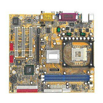
P4MDM/P4MDMP
P4MDUT/P4MDPT
USER'S MANUAL
M/B For Socket 478 Pentium 4 Processor
NO. G03-P4MDMR7A
Release date: Oct. 2003
Trademark:
* Specifications and Information contained in this documentation are furnished for information use only, and are
subject to change at any time without notice, and should not be construed as a commitment by manufacturer.
Advertisement
Table of Contents

Related Manuals for JETWAY P4MDMR7A


Summary of Contents for JETWAY P4MDMR7A
- Page 1 P4MDM/P4MDMP P4MDUT/P4MDPT USER'S MANUAL M/B For Socket 478 Pentium 4 Processor NO. G03-P4MDMR7A Release date: Oct. 2003 Trademark: * Specifications and Information contained in this documentation are furnished for information use only, and are subject to change at any time without notice, and should not be construed as a commitment by manufacturer.
-
Page 2: Table Of Contents
TABLE OF CONTENT USER’S NOTICE ......................1 MANUAL REVISION INFORMATION ................1 COOLING SOLUTIONS ....................1 CHAPTER 1 INTRODUCTION OF P4MDM/P4MDMP/P4MDUT/P4MDPT FEATURE OF MOTHERBOARD ..................2 SPECIFICATION........................3 PERFORMANCE LIST ......................4 LAYOUT DIAGRAM & JUMPER SETTING ..............5 CHAPTER 2 HARDWARE INSTALLATION HARDWARE INSTALLATION STEPS ................ -
Page 3: User's Notice
USER’S NOTICE COPYRIGHT OF THIS MANUAL BELONGS TO THE MANUFACTURER. NO PART OF THIS MANUAL, INCLUDING THE PRODUCTS AND SOFTWARE DESCRIBED IN IT MAY BE REPRODUCED, TRANSMITTED OR TRANSLATED INTO ANY LANGUAGE IN ANY FORM OR BY ANY MEANS WITHOUT WRITTEN PERMISSION OF THE MANUFACTURER. THIS MANUAL CONTAINS ALL INFORMATION REQUIRED TO USE P4MDM/P4MDMP/ P4MDUT/P4MDPT MOTHER-BOARD AND WE DO ASSURE THIS MANUAL MEETS USER’S REQUIREMENT BUT WILL CHANGE, CORRECT ANY TIME WITHOUT NOTICE. -
Page 4: Chapter 1 Introduction Of P4Mdm/P4Mdmp/P4Mdut/P4Mdpt
Introduction of P4MDM/P4MDMP/P4MDUT/P4MDPT Motherboard 1-1 Feature of motherboard The P4MDM/P4MDMP/P4MDUT/P4MDPT motherboard is design for use Intel Pentium 4 Processor in 478 Pin Package Processor with the VIA P4M266/P4M266A(CE) Chipset delivers a high performance and professional desktop platform solution. Which utilize the Socket 478 design and the memory size expandable to 2.0GB. -
Page 5: Performance List
Spec Description ∗ Micro ATX form factor 4 layers PCB size: 24.4x24.4cm Design ∗ VIA P4M266 North Bridge Chipset for P4MDM/ P4MDMP Chipset ∗ VIA P4M266A(CE) Chipset for P4MDUT/ P4MDPT ∗ VIA VT8233A South Bridge Chipset for P4MDM ∗ VIA VT8235 South Bridge Chipset for P4MDMP/P4MDUT/P4MDPT ∗... -
Page 6: Layout Diagram & Jumper Setting
The following performance data list is the testing result of some popular benchmark testing programs. These data are just referred by users, and there is no responsibility for different testing data values gotten by users (the different Hardware & Software configuration will result in different benchmark testing results.) Performance Test Report CPU:... - Page 7 (for P4MDMP/ P4MDPT) PRINT GAME/MIDI PORT PS/2 MOUSE PS/2 Keyboard COM1 LINE-IN LINE-OUT ATX 12V Power Conn. USB Power ON CPU Socket Jumper (JP2) PS2 KB/Mouse Port CPU FAN USB Port /LAN Connector DDR DIMM X2 (for P4MDMP/ P4MDPT) PC99 Back Panel ATX P9 Power Conn.
-
Page 8: Hardware Installation
USB Power On Enable/Disabled 3-pin Block Connectors Connector Name Description Page ATXPWR ATX Power Connector 20-pin Block P.12 ATX12V ATX 12V Power Connector 4-pin Block P.12 ATXP9 ATX P9 Power Connector 6-pin Block P.12 PS2KBM PS/2 Mouse & PS/2 Keyboard 6-pin Female P.13 Connector... -
Page 9: Hardware Installation Steps
2-1 Hardware installation Steps Before using your computer, you had better complete the following steps: 1. Check motherboard jumper setting 2. Install CPU and Fan 3. Install System Memory (DIMM) 4. Install Expansion cards 5. Connect IDE and Floppy cables, Front Panel /Back Panel cable 6. -
Page 10: Install Cpu
1-2 closed USB Power ON Disable 2-3 closed USB Power ON Enabled (Default) USB Power On Setting 2-3 Install CPU 2-3-1 Glossary Chipset (or core logic) - two or more integrated circuits which control the interfaces between the system processor, RAM, I/O devises, and adapter cards. Processor slot/socket - the slot or socket used to mount the system processor on the motherboard. -
Page 11: Install Memory
This motherboard provides a 478-pin surface mount, Zero Insertion Force (ZIF) socket, referred to as the mPGA478B socket supports Intel Pentium 4 processor in the 478 Pin package utilizes Flip-Chip Pin Grid Array (FC-PGA2) package technology. The CPU that comes with the motherboard should have a cooling FAN attached to prevent overheating. -
Page 12: Expansion Card
Figure 2-4 NOTE! When you install DIMM module fully into the DIMM socket the eject tab should be locked into the DIMM module very firmly and fit into its indention on both sides. WARNING! For the DDR SDRAM CLOCK is set at 133MHz, use only DDR266- compliant DDR Modules. -
Page 13: Interrupt Request Table For This Motherboard
Priority Standard function System Timer Keyboard Controller Programmable Interrupt Communications Port (COM2) Communications Port (COM1) Sound Card (sometimes LPT2) Floppy Disk Controller Printer Port (LPT1) System CMOS/Real Time Clock ACPI Mode when enabled 10 * IRQ Holder for PCI Steering 11 * IRQ Holder for PCI Steering 12 *... -
Page 14: Connectors
2-6-1 Connectors Power Connector (20-pin block) : ATXPWR ATX Power Supply connector. This is a new defined 20-pins connector that usually comes with ATX case. The ATX Power Supply allows to use soft power on momentary switch that connect from the front panel switch to 2-pins Power On jumper pole on the motherboard. - Page 15 3.3V 3.3V Power Connector on Motherboard Power Plugs from Power Supply PS/2 Mouse & PS/2 Keyboard Connector: PS2KBM The connectors for PS/2 keyboard and PS/2 Mouse. USB Port connector: USB The connectors are 4-pin connector that connect USB devices to the system board. LAN Port connector: LAN (only for P4MDMP/P4MDPT) This connector is standard RJ45 connector for Network Parallel Port Connector (25-pin female): PARALL...
- Page 16 Pin 1 Floppy Drive Connector (12) Primary IDE Connector (40-pin block): IDE1 This connector supports the provided IDE hard disk ribbon cable. After connecting the single plug end to motherboard, connect the two plugs at other end to your hard disk(s). If you install two hard disks, you must configure the second drive to Slave mode by setting its jumpers accordingly.
-
Page 17: Headers
2-6-2 Headers Serial Port2 COM2 Header (9-pin) : COM2 CO M2 Note: Orient the read marking on the COM2 ribbon cable to pin 1 Pin 1 Serial Port2 COM2 Header Line-Out/MIC Header for Front Panel (9-pin): AUDIO This header connect to Front Panel Line-out, MIC connector with cable. Without install the cable, this header default setting is 5-6 short, 9-10 short. - Page 18 Speaker connector: SPEAK This 4-pin connector connects to the case-mounted speaker. See the figure below. Power LED: PWR LED The Power LED is light on while the system power is on. Connect the Power LED from the system case to this pin. Power switch: PWR BTN This 2-pin connector connects to the case-mounted power switch to power ON/OFF the system.
-
Page 19: Starting Up Your Computer
CPUFAN SYSFAN SFAN1 FAN Speed Headers (11) IR infrared module Headers (5-pin) : IR This connector supports the optional wireless transmitting and receiving infrared module. You must configure the setting through the BIOS setup to use the IR function. Pin 1 IR infrared module Headers (12) CD Audio-In Headers (4-pin) : CD _ IN CD _ IN are the connectors for CD-Audio Input signal. - Page 20 1. After all connection are made, close your computer case cover. 2. Be sure all the switch are off, and check that the power supply input voltage is set to proper position, usually in-put voltage is 220V∼240V or 110V∼120V depending on your country’s voltage used.
-
Page 21: Chapter 3 Introducing Bios
Introducing BIOS The BIOS is a program located on a Flash Memory on the motherboard. This program is a bridge between motherboard and operating system. When you start the computer, the BIOS program gain control. The BIOS first operates an auto-diagnostic test called POST (power on self test) for all the necessary hardware, it detects the entire hardware device and configures the parameters of the hardware synchronization. - Page 22 Once you enter Award BIOS CMOS Setup Utility, the Main Menu (Figure 3-1) will appear on the screen. The Main Menu allows you to select from fourteen setup functions and two exit choices. Use arrow keys to select among the items and press <Enter> to accept or enter the sub-menu.
-
Page 23: Standard Cmos Features
Use this menu to load the BIOS default values these are setting for optimal performances system operations for performance use. Load Standard Defaults Use this menu to load the BIOS default values for the stable performance system operation that are factory settings for normal use. Set Supervisor/User Password Use this menu to set User and Supervisor Passwords. -
Page 24: Advanced Bios Features
Primary Master/Primary Slave Secondary Master/Secondary Slave Press PgUp/<+> or PgDn/<–> to select Manual, None, Auto type. Note that the specifications of your drive must match with the drive table. The hard disk will not work properly if you enter improper information for this category. If your hard disk drive type is not matched or listed, you can use Manual to define your own drive type manually. - Page 25 Allows you to choose the VIRUS Warning feature for IDE Hard Disk boot sector protection. If this function is enabled and someone attempt to write data into this area, BIOS will show a warning message on screen and alarm beep. Disabled (default) No warning message to appear when anything attempts to access the boot sector or hard disk partition table.
-
Page 26: Advanced Chipset Features
Sets the number of times a second to repeat a keystroke when you hold the key down. The settings are: 6, 8, 10, 12, 15, 20, 24, and 30. Typematic Delay (Msec) Sets the delay time after the key is held down before is begins to repeat the keystroke. The settings are 250, 500, 750, and 1000. -
Page 27: Dram Timing Settings
Selecting Enabled allows caching of the system BIOS ROM at F0000h-FFFFFh, resulting in better system performance. However, if any program writes to this memory area, a system error may result. The settings are: Enabled and Disabled. Video RAM Cacheable Select Enabled allows caching of the video BIOS, resulting in better system performance. However, if any program writes to this memory area, a system error may result. -
Page 28: Pci Timing Settings
CMOS Setup Utility – Copyright(C) 1984-2003 Award Software AGP Timing Settings AGP Transfer Aperture Size Item Help AGP Mode Auto AGP Driving Control Auto * AGP Driving Value Menu Level >> AGP Fast Write Disabled AGP Master 1 WS Write Enabled AGP Master 1 WS Read Enabled... -
Page 29: Onchip Ide Function
Please refer to section 3-7-1 OnChip Device Function Please refer to section 3-7-2 Onboard Super IO Function Please refer to section 3-7-3 Init Display First This item allows you to decide to activate whether PCI Slot or AGP VGA first. The settings are: PCI Slot, AGP Slot. -
Page 30: Onchip Device Function
Block mode is also called block transfer, multiple commands, or multiple sector read/write. If your IDE hard drive supports block mode (most new drives do), select Enabled for automatic detection of the optimal number of block read/writes per sector the drive can support. The settings are: Enabled, Disabled. -
Page 31: Power Management Setup
CMOS Setup Utility – Copyright(C) 1984-2003 Award Software Onboard Super IO Function Onboard FDD Controller Enabled Item Help Onboard Serial Port 1 3F8/IRQ4 Onboard Serial Port 2 2F8/IRQ3 UART2 Mode Normal Menu Level >> RxD, TxD Active Hi, Lo IR Duplex Mode Half Use IR Pins IRRX/IRTX... -
Page 32: Pm Wake Up Events
The Power Management Setup allows you to configure your system to most effectively save energy saving while operating in a manner consistent with your own style of computer use. CMOS Setup Utility – Copyright(C) 1984-2003 Award Software Power Management Setup ACPI Function Enabled Item Help... -
Page 33: 3-8-1.1 Irqs Activities
CMOS Setup Utility – Copyright(C) 1984-2003 Award Software Wake Up Events Item Help LPT & COM LPT/COM HDD & FDD PCI Master Menu Level >> Wake-Up on Ring/LAN Disabled Wake-Up on PCI PME Disabled Wake-Up on RTC Alarm Disabled x Date of Month Alarm x Time (hh:mm:ss) Alarm 0 : 0 : 0 >... -
Page 34: Irq Resources
This section describes configuring the PCI bus system. PCI, or Personal Computer Interconnect, is a system which allows I/O devices to operate at speeds nearing the speed the CPU itself uses when communicating with its own special components. This section covers some very technical items and it is strongly recommended that only experienced users should make any changes to the default settings. -
Page 35: Irq Resources
CMOS Setup Utility – Copyright(C) 1984-2003 Award Software IRQ Resources IRQ3 assigned to PCI Device Item Help IRQ4 assigned to PCI Device IRQ5 assigned to PCI Device IRQ7 assigned to PCI Device Menu Level >> IRQ9 assigned to PCI Device IRQ10 assigned to PCI Device... -
Page 36: Load Standard/Optimized Defaults
This section is for setting CPU Frequency/Voltage Control. CMOS Setup Utility – Copyright(C) 1984-2003 Award Software Miscellaneous Control CPU Clock Ratio Item Help Auto Detect DIMM/PCI Clk Enabled Spread Spectrum Disabled ** Current Host/PCI Clock is 100/33MHz ** Menu Level > Host/PCI Clock at Next Boot is 100/33MHz ** Current DRAM Clock is 133MHz **... -
Page 37: Set Supervisor/User Password
Load Standard Defaults When you press <Enter> on this item, you get confirmation dialog box with a message similar Load Standard Defaults (Y/N)? N Pressing <Y> loads the BIOS default values for the most stable, minimal-performance system operations. Load Optimized Defaults When you press <Enter>... -
Page 38: Chapter 4 Driver & Free Program Installation
DRIVER & FREE PROGRAM INSTALLATION Check your package and there is A MAGIC INSTALL CD included. This CD consists of all DRIVERS you need and some free application programs and utility programs. In addition, this CD also include an auto detect software which can tell you which hardware is installed, and which DRIVERS needed so that your system can function properly. - Page 39 IDE : VIA ATAPI VENDOR SUPPORT DRIVER IS USED TO FIXED COMPATIBILITY ISSUE FOR IDE DEVICES AGPVXD : VIA AGPVXD DRIVER IS TO BE INSTALLED, IF YOU ARE USING AN AGP VGA CARD, VIAGART.VXD WILL PROVIDE SERVICE ROUTINES TO YOUR VGA DRIVER AND INTERFACE DIRECTLY TO HARDWARE, PROVIDING FAST GRAPHIC ACCESS IRQ ROUTING :...
-
Page 40: Vga Install Via P4M266 Vga Driver
7. Click NEXT to Install VIA AGP VXD Driver 8. Click NEXT to Install VIA IRQ Routing Mini port Driver 9. Click Finish to restart computer 4-2 VGA install VIA P4M266 VGA Driver For WINDOWS 9X/ME/NT4.0/2000/XP 1. Click VGA when MAGIC INSTALL MENU Click NEXT When ProSavageDDR Driver appears Install Setup Wizard Appears... -
Page 41: Sound Install Alc/Cmi Audio Codec Driver
4-3 Sound Install ALC/CMI Audio Codec Driver 4-3-1 Install ALC Audio Codec Driver 1. Click SOUND when MAGIC INSTALL 2. Then auto detect operation system language MENU appears edition, click OK, start to install DRIVER 3. Click Finish and Restart Windows 4. - Page 42 4-3-2 SOUND Install CMI Audio Codec Driver 3. Click SOUND when MAGIC INSTALL 4. Choose Install component in Installation MENU appears Package 3. Click Next when copyright Issue appears, click 4. Enter Program folders name or click Next Next or choose BROWSE to change the path for the file to be store 5.
-
Page 43: Lan Install Via10/100Mb Lan Controller Driver
9. C-Media Multi-Channel Audio Demo Program, 10. When Enabled XeaR, you can plug earphone you can Test speaker position in Speak-Out connector as a Rear speaker, and 2-channel speaker plug in Line-In as Front Speaker to get 4-channel effect 4-4 LAN Install VIA10/100MB LAN Controller Driver (Only for P4MDMP/P4MDPT) The VIA10/100MB PCI Ethernet Adapter Driver path is X:\VIA\LANDRV Click LAN when Magic Install Menu appear 2. - Page 44 Software The path of the file is X:\VIA\HEALTH-W\SETUP.EXE (Support Windows 9X/ME/2K/NT/XP) In Windows 95/98 Winbond Hardware Doctor Monitoring Software needs some system files to copy in Utility that’s why it needs install PC-HEALTH twice to complete setup. 1. Click PC-Health when Magic Install Menu 2.
-
Page 45: Magic Bios Install Bios Live Update Utility
4-6 MAGIC BIOS Install BIOS Live Update Utility Click Magic BIOS when Magic Install Click Next to install the Magic BIOS in MENU appears Destination Folder After finish Setup you will have a Magic Double click the Magic BIOS icon you will BIOS icon in your screen have this picture, choose from internet you can upgrade BIOS On-line... -
Page 46: Usb2.0
When choose From Local Driver to update 10. Choose the correct BIOS file to update BIOS BIOS, you must have the correct BIOS file in your Local Driver 4-7 USB2.0 Install VIA USB2.0 Device Driver (Only for P4MDMP/P4MDUT/P4MDPT) 1. Click USB2.0 when MAGIC INSTALL 2. -
Page 47: Pc-Cillin Install Pc-Cillin2002 Anti-Virus Program
4-8 PC-CILLIN Install PC-CILLIN 2002 Anti-virus program 1. Click PC-CILLIN when MAGIC INSTALL 2. (1) Click "Install PC-CILLIN" when PC- MENU appear CILLIN 2002 main menu appears, and Click NEXT when "Install Shield Wizard For PC- CILLIN 2002" (2) Click Open Manual. you can learn PC- CILLIN 2002 how to use 3. -
Page 48: How To Disable On-Board Sound
7. After PC-CILLIN 2002 complete, Please 8. finish register process, we recommend select register your information and get LICENSE update item to download newest engine code KEY from TREND MICRO web site, enter and virus code your license key and click FINISH Note : Please install ACROBAT READER, Before you read PC-CILLIN 2002 User Manual, the path at X:\acrobat\ar500eng.exe...
Need help?
Do you have a question about the P4MDMR7A and is the answer not in the manual?
Questions and answers