Table of Contents
Advertisement
Quick Links
P4845DDA/P4845EDA
USER'S MANUAL
M/B For Socket 478 Pentium 4 Processor
NO. G03-P4845DDA2A
Release date: Nov. 2002
Trademark:
* Specifications and Information contained in this documentation are furnished for information use only, and are
subject to change at any time without notice, and should not be construed as a commitment by manufacturer.
Advertisement
Table of Contents

Subscribe to Our Youtube Channel
Related Manuals for JETWAY P4845DDA


Summary of Contents for JETWAY P4845DDA
- Page 1 P4845DDA/P4845EDA USER'S MANUAL M/B For Socket 478 Pentium 4 Processor NO. G03-P4845DDA2A Release date: Nov. 2002 Trademark: * Specifications and Information contained in this documentation are furnished for information use only, and are subject to change at any time without notice, and should not be construed as a commitment by manufacturer.
-
Page 2: Table Of Contents
TABLE OF CONTENT USER’S NOTICE ......................1 MANUAL REVISION INFORMATION ................1 COOLING SOLUTIONS ....................1 CHAPTER 1 INTRODUCTION OF P4845DDA/P4845EDA MOTHERBOARD 1-1 FEATURE OF MOTHERBOARD ................2 1-2 SPECIFICATION .....................3 1-3 PERFORMANCE LIST....................4 1-4 LAYOUT DIAGRAM & JUMPER SETTING............5 CHAPTER 2 HARDWARE INSTALLATION 2-1 HARDWARE INSTALLATION STEPS ..............7... -
Page 3: User's Notice
REPRODUCED, TRANSMITTED OR TRANSLATED INTO ANY LANGUAGE IN ANY FORM OR BY ANY MEANS WITHOUT WRITTEN PERMISSION OF THE MANUFACTURER. THIS MANUAL CONTAINS ALL INFORMATION REQUIRED TO USE P4845DDA/P4845EDA MOTHER-BOARD AND WE DO ASSURE THIS MANUAL MEETS USER’S REQUIREMENT BUT WILL CHANGE, CORRECT ANY TIME WITHOUT NOTICE. -
Page 4: Chapter 1 Introduction Of P4845Dda/P4845Eda Motherboard
Introduction of P4845DDA/P4845EDA Motherboard 1-1 Feature of motherboard The P4845DDA/P4845EDA motherboard is design for use Intel Pentium 4 Processor in 478 Pin Package/Northwood Processor with the Intel 845D/845E Chipset delivers a high performance and professional desktop platform solution. Which utilize the Socket 478 design and the memory size expandable to 2.0GB. -
Page 5: Specification
∗ ATX form factor 4 layers PCB size: 30.5x21.0cm Design ∗ Intel 845D Memory Controller Hub (MCH) Chipset Chipset for P4845DDA ∗ Intel 845E Memory Controller Hub (MCH) Chipset for P4845EDA ∗ Intel 82801BA I/O Controller Hub (ICH2) Chipset ∗ Support Intel Pentium 4 478 Pin package utilizes Flip-... -
Page 6: Performance List
1-3 Performance List The following performance data list is the testing result of some popular benchmark testing programs. These data are just referred by users, and there is no responsibility for different testing data values gotten by users (the different Hardware & Software configuration will result in different benchmark testing results.) Performance Test Report CPU:... -
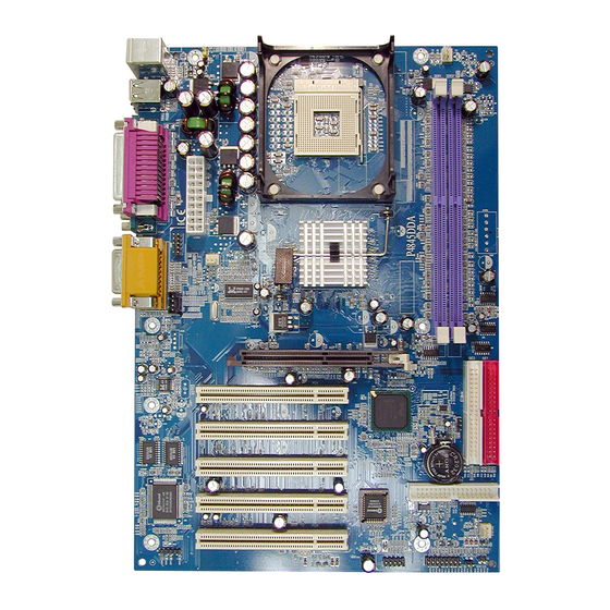
Page 7: Layout Diagram & Jumper Setting
DEMO2 150.1 1-4 Layout Diagram & Jumper Setting PRINT GAME/MIDI PORT PS/2 Mouse PS/2 Keyboard LINE-IN COM1 COM2 LINE-OUT K/B Power ON (JP1) CPU Socket PS2 KB/Mouse Port CPU FAN USB Port ATX Power Conn. PC99 Back Panel DDR DIMM X2 Intel 845D Chipset Front Panel Audio SYSFAN... - Page 8 Jumpers Jumper Name Description Page JP10 CMOS RAM Clear 3-pin Block Keyboard Power On Enable/Disabled 3-pin Block Connectors Connector Name Description Page ATXPWR ATX Power Connector 20-pin Block P.12 PS/2 Mouse & PS/2 Keyboard 6-pin Female P.13 Connector (KB/MOUSE) J2 (USB) USB Port Connector 4-pin Connector P.13...
-
Page 9: Hardware Installation Steps
Chapter 2 Hardware installation 2-1 Hardware installation Steps Before using your computer, you had better complete the following steps: 1. Check motherboard jumper setting 2. Install CPU and Fan 3. Install System Memory (DIMM) 4. Install Expansion cards 5. Connect IDE and Floppy cables, Front Panel /Back Panel cable 6. -
Page 10: Glossary
JP10 JP10 1-2 closed Normal (Default) 2-3 closed Clear CMOS CMOS RAM Clear Setting (2) Keyboard Power On function Enabled/Disabled: JP1 When setting Enabled you can using keyboard by key in password to power on system. 1-2 closed K/B Power ON Disable 2-3 closed K/B Power ON Enabled (Default) Keyboard Power On Setting... -
Page 11: About Intel Pentium 4 478-Pin Cpu
LAN (interface) - Local Area Network - the interface to your local area network. BIOS (Basic Input/Output System) - the program logic used to boot up a computer and establish the relationship between the various components. Driver - software, which defines the characteristics of a device for use by another device or other software. -
Page 12: Expansion Card
This motherboard provides 184-pin DUAL INLINE MEMORY MODULES (DIMM) sites for memory expansion available from minimum memory size of 64MB to maximum memory size of 2.0GB DDR SDRAM. Valid Memory Configurations Bank 184-Pin DIMM Total Memory Bank 0, 1 (DDR1) DDR200/DDR266 64MB∼1.0GB DDR SDRAM Module... -
Page 13: Assigning Irq For Expansion Card
1. Read the documentation for your expansion card and make any necessary hardware or software setting for your expansion card such as jumpers. 2. Remove your computer’s cover and the bracket plate on the slot you intend to use. 3. Align the card’s connectors and press firmly. 4. -
Page 14: Agp Slot
√ Slot 5 Onboard VGA √ Onboard USB 1 √ Onboard USB 2 √ AC97/MC97 IMPORTANT! If using PCI cards on shared slots, make sure that the drivers support “Shared IRQ” or that the cards don’t need IRQ assignments. Conflicts will arise between the two PCI groups that will make the system unstable or cards inoperable. -
Page 15: Connectors
2-6-1 Connectors Power Connector (20-pin block) : ATXPWR ATX Power Supply connector. This is a new defined 20-pins connector that usually comes with ATX case. The ATX Power Supply allows to use soft power on momentary switch that connect from the front panel switch to 2-pins Power On jumper pole on the motherboard. - Page 16 PS/2 Mouse PRINT GAME/MIDI PORT LINE-IN COM1 COM2 PS/2 Keyboard LINE-OUT Floppy drive Connector (34-pin block): FDD This connector supports the provided floppy drive ribbon cable. After connecting the single plug end to motherboard, connect the two plugs at other end to the floppy drives. Pin 1 Floppy Drive Connector Primary IDE Connector (40-pin block): IDE1...
-
Page 17: Headers
IDE 2 IDE 1 Pin 1 Pin 1 Secondary IDE Connector Primary IDE Connector • Two hard disks can be connected to each connector. The first HDD is referred to as the “Master” and the second HDD is referred to as the “Slave”. •... - Page 18 USB1 Pin 1 USB Port Headers IDE Activity LED: IDE LED This connector connects to the hard disk activity indicator light on the case. Turbo LED switch: TURBO LED Since the motherboard’s turbo function is always on. The turbo LED will remain constantly on while the system power is on.
- Page 19 PWR BTN IDE LE D Speaker System Case Connections Wake On-LAN Headers (3-pin) : WOL This connector connects to a LAN card with a WAKE ON-LAN output. This connector power up the system when a wake up signal is received through the LAN card.
-
Page 20: Starting Up Your Computer
CPUFAN SYSFAN SYSFAN2 FAN Headers (11) IR infrared module Headers (5-pin) : IR This connector supports the optional wireless transmitting and receiving infrared module. You must configure the setting through the BIOS setup to use the IR function. Infrared Module Headers (12) CD Audio-In Headers (4-pin) : CDIN CDIN are the connectors for CD-Audio Input signal. - Page 21 1. After all connection are made, close your computer case cover. 2. Be sure all the switch are off, and check that the power supply input voltage is set to proper position, usually in-put voltage is 220V∼240V or 110V∼120V depending on your country’s voltage used.
-
Page 22: Entering Setup
Chapter 3 Introducing BIOS The BIOS is a program located on a Flash Memory on the motherboard. This program is a bridge between motherboard and operating system. When you start the computer, the BIOS program gain control. The BIOS first operates an auto-diagnostic test called POST (power on self test) for all the necessary hardware, it detects the entire hardware device and configures the parameters of the hardware synchronization. -
Page 23: The Main Menu
3-3 The Main Menu Once you enter Award ® BIOS CMOS Setup Utility, the Main Menu (Figure 3-1) will appear on the screen. The Main Menu allows you to select from fourteen setup functions and two exit choices. Use arrow keys to select among the items and press <Enter> to accept or enter the sub-menu. -
Page 24: Standard Cmos Features
Use this menu to specify your settings for Miscellaneous control. Load Optimized Defaults Use this menu to load the BIOS default values that are settings for optimal performances system operations. Load Standard Defaults Use this menu to load the BIOS default values that are factory settings for the stable performance system operation. -
Page 25: Advanced Bios Features
Time The time format is <hour><minute><second>. Primary Master/Primary Slave Secondary Master/Secondary Slave Press PgUp/<+> or PgDn/<–> to select Manual, None, Auto type. Note that the specifications of your drive must match with the drive table. The hard disk will not work properly if you enter improper information for this category. - Page 26 Anti-Virus Protection Allows you to choose the VIRUS Warning feature for IDE Hard Disk boot sector protection. If this function is enabled and someone attempt to write data into this area, BIOS will show a warning message on screen and alarm beep. Disabled (default) No warning message to appear when anything attempts to access the boot sector or hard disk partition table.
-
Page 27: Advanced Chipset Features
Typematic Rate Setting Keystrokes repeat at a rate determined by the keyboard controller. When enabled, the typematic rate and typematic delay can be selected. The settings are: Enabled/Disabled. Typematic Rate (Chars/Sec) Sets the number of times a second to repeat a keystroke when you hold the key down. The settings are: 6, 8, 10, 12, 15, 20, 24, and 30. -
Page 28: Dram Timing Settings
Video RAM Cacheable Select Enabled allows caching of the video BIOS, resulting in better system performance. However, if any program writes to this memory area, a system error may result. The settings are: Enabled and Disabled. Memory Hole At 15M-16M You can reserve this area of system memory for ISA adapter ROM. -
Page 29: Integrated Peripherals
3-7 Integrated Peripherals CMOS Setup Utility – Copyright(C) 1984-2002 Award Software Integrated Peripherals > Onboard IDE Function Press Enter Item Help > Onboard Device Function Press Enter > Onboard Super IO Function Press Enter Init Display First PCI Slot Menu Level > Power On Function Button Only KB Power On Password... - Page 30 OnChip IDE Channal0/Channel1 The integrated peripheral controller contains an IDE interface with support for two IDE channels. Select Enabled to activate each channel separately. The settings are: Enabled and Disabled. Primary/Secondary Master/Slave PIO The four IDE PIO (Programmed Input/Output) fields let you set a PIO mode (0-4) for each of the four IDE devices that the onboard IDE interface supports.
- Page 31 This item allows you to decide to enable/disable the chipset family to support AC97 Modem. The settings are: Auto, Disabled. USB Controller Select Enabled if your system contains a Universal Serial Bus (USB) controller and you have a USB peripherals. The settings are: Enabled, Disabled. USB Keyboard Legacy Support Select Enabled if your system contains a Universal Serial Bus (USB) controller and you have a USB keyboard.
-
Page 32: Power Management Setup
(378H/IRQ7) Line Printer port 1 Parallel Port Mode : Standard Parallel Port : Enhanced Parallel Port : Extended Capability Port SPP/EPP/ECP/ECP+EPP To operate the onboard parallel port as Standard Parallel Port only, choose “SPP.” To operate the onboard parallel port in the EPP modes simultaneously, choose “EPP.” By choosing “ECP”, the onboard parallel port will operate in ECP mode only. - Page 33 ACPI Function This item allows you to Enabled/Disabled the Advanced Configuration and Power Management (ACPI). The settings are Enabled and Disabled. ACPI Suspend Type This item allows you to select ACPI Suspend Type. The setting are: S1(POS), S3(STR) Video Off in Suspend This determines the manner in which the monitor is blanked.
-
Page 34: Pm Timer Reload Events
3-8-1 PM Timer Reload Events CMOS Setup Utility – Copyright(C) 1984-2002 Award Software PM Timer Reload Events Primary IDE 0 Disabled Item Help Primary IDE 1 Disabled Secondary IDE 0 Disabled Secondary IDE 1 Disabled Menu Level >> FDD, COM, LPT Port Disabled PCI PIRQ [A-D] # Disabled... -
Page 35: Irq Resources
follows this field (a sub menu is preceded by a “>”). The settings are: Auto(ESCD), Manual. IRQ Resources When resources are controlled manually, assign each system interrupt a type, depending on the type of device using the interrupt. Please refer to section 3-9-1 PCI/VGA Palette Snoop Leave this field at Disabled. -
Page 36: Miscellaneous Control
25 ° C Current System Temperature 38 ° C Menu Level > Current CPU Temperature Current CPUFAN Speed 5000 rpm Current SYSFAN Speed 5000 rpm Current SYSFAN2 Speed 5000 rpm Vcore 1.71V Vcc1.5 1.51V Vcc3.3 3.31V + 5V 4.98V +12V 12.22V -12V -12.36V... -
Page 37: Load Standard/Optimized Defaults
This item allows you to select CPU frequency step by step increasing. The choice are: 100MHz∼200MHz DRAM Clock at Next Boot is This item allows you select the DRAM Clock same as Host clock, or can add 33MHz when Host Clock under 109MHz. -
Page 38: Magic Install Supports Windows 95/98/98Se/Nt4.0/2000/Xp
When a password has been enabled, you will be prompted to enter it every time you try to enter Setup. This prevents an unauthorized person from changing any part of your system configuration. Additionally, when a password is enabled, you can also require the BIOS to request a password every time your system is rebooted. -
Page 39: Inf Install Intel 845 Chipset System Driver
From MAGIC INSTALL MENU you may make 9 selections: 1. INF install Intel 845 chipset system driver 2. SOUND install ALC Audio Codec driver 3. DIRECTX8 install Microsoft DirectX 8.0 driver 4. PC-CILLIN install PC-CILLIN2002 anti-virus program 5. PC-HEALTH install Intel 845 PC-HEALTH monitor 6. -
Page 40: Sound Install Alc Audio Codec Driver
NOTE: MAGIC INSTALL will auto detect file path X:\INTEL845\INF\SETUP.EXE This driver supports WINDOWS 95/98/98SE/ME/2000/XP (NT4.0 do not require) 4-2 SOUND Install ALC Audio Codec Driver 1. Click SOUND when MAGIC INSTALL 2. Then auto detect operation system language MENU appears edition, click Next, start to install DRIVER 3. -
Page 41: Pc-Health Intel 845 Pc-Health Monitor
5. Avance Audio Rack table can play CD, WAV, 6. This is a Sound Environment Simulator and MID, MP3, AVI, MPG Format File Karaok function table NOTE: MAGIC INSTALL will auto detect file path: X:\CODEC\ALC201\SETUP.EXE (for WINDOWS 95/98/98SE/ME/NT4.0/2000/XP) 4-3 PC-HEALTH Intel 845 PC-Health Monitor The path of the file is X:\INTEL845\HW30\SETUP.EXE (Only support WINDOWS 95/98/98SE/ME) In Windows 95/98 Winbond Hardware Doctor Monitoring Software needs some system files to copy in Utility that’s why it needs install PC-HEALTH twice to complete setup. -
Page 42: Magic Bios Install Bios Live Update Utility
4-3-1 How To Utilize PC-HEALTH Click Program → Winbond Hardware Doctor 2. After executing Winbond Hardware Doctor it → Hardware Doctor the Winbond Hardware supports system voltage, Fan speed and Doctor will appears CPU/SYSTEM Temperature. Because this is a You can remove the Utility in Control Panel On-time Monitoring program therefore the →... - Page 43 After finish Setup you will have a Magic Double click the Magic BIOS icon you will BIOS icon in your screen have this picture, choose from internet you can upgrade BIOS On-line When On-line update BIOS the program Click Next if you need update BIOS, after will auto-check your BIOS version upgrade BIOS, the system will clear CMOS and automatically restart...
-
Page 44: Iaa Install Intel Application Accelerator Software
When choose From Local Driver to update 10. Choose the correct BIOS file to update BIOS BIOS, you must have the correct BIOS file in your Local Driver 4-5 IAA Install Application Accelerator Software The Intel Application Accelerator is designed to improve performance of the storage sub-system and overall system performance. - Page 45 Click PC-CILLIN when MAGIC INSTALL 2. (1) Click "Install PC-CILLIN" when PC- MENU appear CILLIN 2002 main menu appears, and Click NEXT when "Install Shield Wizard For PC- CILLIN 2002" (2) Click Open Manual. you can learn PC- CILLIN 2002 how to use This is license agreement, select "I Accept Click NEXT and Enter your Customer the terms"...
-
Page 46: How To Disable On-Board Sound
You may copy from DRIVER CD X:\FLASH\AWDFLASH.EXE or download from our web site. STEP 3. Copy latest BIOS for P4845DDA/P4845EDA from our web site to your boot disc. STEP 4. Insert your boot disc into A:, start the computer, type “Awdflash A:\P4845DAxxx.BIN /SN/PY/CC/R”... - Page 47 STEP 5. Push ENTER and the BIOS will be updated, computer will be restarted automatically...
Need help?
Do you have a question about the P4845DDA and is the answer not in the manual?
Questions and answers