Table of Contents
Advertisement
M/B For Socket 370 Pentium
Trademark:
∗
Pentium is registered trademark and Celeron is a trademark of Intel corporation,
the other names and brands are the property of their respective owners.
∗
Specifications and Information contained in this documentation are furnished for information use only, and are
subject to change at any time without notice, and should not be construed as a commitment by manufacturer.
694TAS
USER'S MANUAL
NO. G03-694TAS3A
Release date: May 2002
III Processor
Advertisement
Table of Contents

Related Manuals for JETWAY 694TAS3A


Summary of Contents for JETWAY 694TAS3A
- Page 1 694TAS USER'S MANUAL M/B For Socket 370 Pentium III Processor NO. G03-694TAS3A Release date: May 2002 Trademark: ∗ Pentium is registered trademark and Celeron is a trademark of Intel corporation, the other names and brands are the property of their respective owners.
-
Page 2: Table Of Contents
TABLE OF CONTENT USER’S NOTICE ................1 MANUAL REVISION INFORMATION ..........2 COOLING SOLUTIONS..............2 CHAPTER 1 INTRODUCTION OF 694TAS MOTHERBOARD 1-1 FEATURE OF MOTHERBOARD............... 3 1-2 SPECIFICATION ..................4 1-3 PERFORMANCE LIST ................5 1-4 LAYOUT & JUMPER SETTING ..............6 CHAPTER 2 HARDWARE INSTALLATION 2-1 HARDWARE INSTALLATION STEPS............. - Page 3 3-8 POWER MANAGEMENT SETUP.............. 35 3-8-1 POWER MANAGEMENT ............... 36 3-8-2 WAKE UP EVENTS ................. 37 3-8-2.1 IRQS ACTIVITY ................3-9 PNP/PCI CONFIGURATION SETUP ............38 3-10 PC HEALTH STATUS................. 39 3-11 MISCELLANEOUS CONTROL ............... 40 3-12 LOAD STANDARD/OPTIMIZED DEFAULTS ........41 3-13 SET SUPERVISOR/USER PASSWORD...........
-
Page 4: User's Notice
USER’S NOTICE COPYRIGHT OF THIS MANUAL BELONGS TO MANUFACTURER. NO PART OF THIS MANUAL, INCLUDING THE PRODUCTS AND SOFTWARE DESCRIBED IN IT MAY BE REPRODUCED, TRANSMITTED OR TRANSLATED INTO ANY LANGUAGE IN ANY FORM OR BY ANY MEANS WITHOUT WRITTEN PERMISSION OF MANUFACTURER. -
Page 5: Manual Revision Information
Manual Revision Information Reversion Revision History Date Third Edition May 2002 Item Checklist 694TAS Cable for IDE/Floppy CD for motherboard utilities Cable for USB Port 3/4 (Option) □ 694TAS User’s Manual Intel Processor Family Thermal Solutions As processor technology pushes to faster speeds and higher performance, thermal management becomes increasingly crucial when building computer systems. -
Page 6: Chapter 1 Introduction Of 694Tas Motherboard
Chapter 1 Introduction of 694TAS Motherboard 1-1 Feature of motherboard The 694TAS motherboard is design for use Intel PentiumIII /Celeron/Tualatin FC-PGA CPU, which utilize the Socket 370 design and the memory size expandable to 1.5GB. This motherboard use the newest VIA Apollo Pro VT82C694T chipset, whose 133MHz front side bus &... -
Page 7: Specification
1-2 Specification Spec Description ∗ ATX form factor 4 layers PCB size: 30.5x19.0cm Design ∗ VIA Apollo Pro VT82C694T/82C686B Chipset Chipset ∗ Support Intel Pentium III /Celeron/Tualatin FC-PGA CPU Socket 370 ∗ Support Front Side Bus 66Mhz/100Mhz/133Mhz CPU ∗ 168-pin DIMM socket x 3 Memory Socket ∗... -
Page 8: Performance List
1-3 Performance List The following performance data list is the testing result of some popular benchmark testing programs. These data are just referred by users, and there is no responsibility for different testing data values gotten by users (the different Hardware & Software configuration will result in different benchmark testing results.) ... -
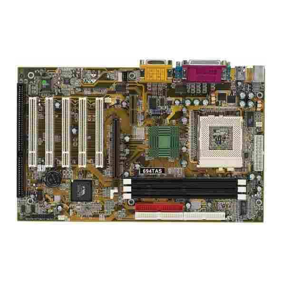
Page 9: Layout & Jumper Setting
1-4 Layout & Jumper Setting PS/2 MOUSE PRINT GAME/MIDI PORT PS/2 KEYBOARD COM1 COM2 LINE-OUT LINE-IN C O M 2 C O M 1 PS/2 G AME MO USE PR INT AC97 & K/B CO DE C BIO S LINE-IN LINE-O UT USB_A PS2KB-MS FAN2... -
Page 10: Expansion Sockets
Jumpers Jumper Name Description Page JK1, JK2 CPU Bus Frequency Selection 3-pin Block p. 8 BSEL0, BSEL1 2-pin Block CPU Ratio Selector 2x4-pin Block p. 8 VIA C3 CPU Selection 2-pin Block p. 9 JBAT CMOS RAM Clear 3-pin Block p. -
Page 11: Chapter 2 Hardware Installation
Chapter 2 Hardware installation 2-1 Hardware installation Steps Before using your computer, you had better complete the following steps: 1. Check motherboard setting 2. Install CPU 3. Install Memory 4. Install Expansion cards 5. Connect Ribbon cables, Panel wires, and power supply 6. - Page 12 CPU Ratio Selector Table for the Pentium III and Celeron Socket 370 CPU Celeron Pentium III Pentium III Speed Ratio Speed Ratio Speed Ratio 566/66 66MHz 8.5x 500E/100 100MHz 5.0x 750/100 100MHz 7.5x 600/66 66MHz 9.0x 533EB/133 133MHz 4.0x 800/100 100MHz 8.0x 633/66...
-
Page 13: Install Cpu
JBAT JBAT 1-2 closed Normal 2-3 closed Clear CMOS (default) CMOS RAM Clear Setting 2-3 Install CPU 2-3-1 Glossary Chipset (or core logic) - two or more integrated circuits which control the interfaces between the system processor, RAM, I/O devises, and adapter cards. Processor slot/socket - the slot or socket used to mount the system processor on the motherboard. -
Page 14: Install Cpu
2-3-2 Install CPU This motherboard Provides a ZIF Socket 370. The CPU that comes with the motherboard should have a cooling FAN attached to prevent overheating. If this is not the case, then purchase a correct cooling FAN before you turn on your system. WARNING! Be sure that there is sufficient air circulation across the processor’s heatsink and CPU cooling FAN is working correctly, otherwise it may... -
Page 15: Install Memory
CMOS Setup Utility – Copyright(C) 1984-2000 Award Software Miscellaneous Control CyrixIII Clock Ratio Default Item Help Auto Detect DIMM/PCI Clock Enabled Spread Spectrum Disabled ** Current Host Clock is 66Mhz ** Menu Level > Host Clock at Next Boot is 66Mhz ** Current DRAM Clock is 66Mhz **... -
Page 16: Expansion Card
Generally, installing SDRAM modules to your motherboard is very easy, you can refer to figure 2-4 to see what a 168-Pin PC100 & PC133 SDRAM module looks like. DIMM1 (BANK0+BANK1) DIMM2 (BANK2+ BANK3) Figure 2-4 DIMM3 (BANK4+ BANK5) NOTE! When you install DIMM module fully into the DIMM socket the eject tab should be locked into the DIMM module very fimly and fit into its indention on both sides. -
Page 17: Assigning Irq For Expansion Card
2-5-2 Assigning IRQs For Expansion Card Some expansion cards need an IRQ to operate. Generally, an IRQ must exclusively assign to one use. In a standard design, there are 16 IRQs available but most of them are already in use. Standard Interrupt Assignments Priority Standard function... -
Page 18: Agp Slot
This motherboard provides an AGP Slot, support the 1X/2X/4X AGP VGA card. 2-6 Connectors, Headers 2-6-1 Connectors Power Connector (20-pin block) : POWER ATX Power Supply connector. This is a new defined 20-pins connector that usually comes with ATX case. The ATX Power Supply allows to use soft power on momentary switch that connect from the front panel switch to 2-pins Power On jumper pole on the motherboard. - Page 19 USB PORT 1 USB PORT 2 Parallel Port Connector (25-pin female) : Parallel Port connector is a 25-pin D-Subminiature Receptacle connector. The On- board Parallel Port can be disabled through the BIOS SETUP. Please refer to Chapter 3 “INTEGRATED PERIPHERALS SETUP” section for more detail information. Parallel Port Audio and Game Connector : AUD _ GAME This Connector are 3 phone Jack for LINE-OUT, LINE-IN, MIC and a 15-pin...
- Page 20 COM1 COM2 Floppy drive Connector (34-pin block): FDD This connector supports the provided floppy drive ribbon cable. After connecting the single plug end to motherboard, connect the two plugs at other end to the floppy drives. Pin 1 Floppy Drive Connector Primary IDE Connector (40-pin block): IDE1 This connector supports the provided IDE hard disk ribbon cable.
-
Page 21: Headers
• Two hard disks can be connected to each connector. The first HDD is referred to as the “Master” and the second HDD is referred to as the “Slave”. • For performance issues, we strongly suggest you don’t install a CD-ROM or DVD-ROM drive on the same IDE channel as a hard disk. - Page 22 IDE LE D PW BTN System Case Connections (8) Wake On-LAN Headers (3-pin) : WOL This connector connects to a LAN card with a WAKE ON-LAN output. This connector power up the system when a wake up signal is received through the LAN card. NOTE: This feature requires that Wake On LAN or Ring In Wake up is enabled.
- Page 23 (10) IR infrared module Headers (5-pin) : IR This connector supports the optional wireless transmitting and receiving infrared module. You must configure the setting through the BIOS setup to use the IR function. VC C IR R X G ND IR TX Infrared Module Headers (11) CD Audio-In Headers (4-pin) : CD_IN1...
-
Page 24: Starting Up Your Computer
2-7 Starting Up Your Computer 1. After all connection are made, close your computer case cover. 2. Be sure all the switch are off, and check that the power supply input voltage is set to proper position, usually in-put voltage is 220V∼240V or 110V∼120V depending on your country’s voltage used. -
Page 25: Chapter 3 Introducing Bios
Chapter 3 Introducing BIOS The BIOS is a program located on a Flash Memory on the motherboard. This program is a bridge between motherboard and operating system. When you start the computer, the BIOS program gain control. The BIOS first operates an auto-diagnostic test called POST (power on self test) for all the necessary hardware, it detects the entire hardware device and configures the parameters of the hardware synchronization. -
Page 26: Getting Help
3-2 Getting Help Main Menu The on-line description of the highlighted setup function is displayed at the bottom of the screen. Status Page Setup Menu/Option Page Setup Menu Press F1 to pop up a small help window that describes the appropriate keys to use and the possible selections for the highlighted item. - Page 27 Advanced Chipset Features Use this menu to change the values in the chipset registers and optimize your system’s performance. Integrated Peripherals Use this menu to specify your settings for integrated peripherals. Power Management Setup Use this menu to specify your settings for power management. PnP/PCI configurations This entry appears if your system supports PnP/PCI.
-
Page 28: Standard Cmos Features
3-4 Standard CMOS Features The items in Standard CMOS Setup Menu are divided into several categories. Each category includes no, one or more than one setup items. Use the arrow keys to highlight the item and then use the <PgUp> or <PgDn> keys to select the value you want in each item. CMOS Setup Utility –... -
Page 29: Advanced Bios Features
If the controller of HDD interface is CD-ROM, the selection shall be “None” Access Mode The settings are Auto Normal, Large, and LBA. Cylinder number of cylinders Head number of heads Precomp write precomp landing zone Landing Zone Sector number of sectors 3-5 Advanced BIOS Features CMOS Setup Utility –... - Page 30 CPU L1 Cache The default value is Enabled. Enabled (default) Enable cache Disabled Disable cache Note: The internal cache is built in the processor. CPU L2 Cache Choose Enabled or Disabled. This option enables the Level 2 cache memory. CPU L2 Cache ECC Checking Choose Enabled or Disabled.
-
Page 31: Advanced Chipset Features
Typematic Rate (Chars/Sec) Sets the number of times a second to repeat a keystroke when you hold the key down. The settings are: 6, 8, 10, 12, 15, 20, 24, and 30. Typematic Delay (Msec) Sets the delay time after the key is held down before is begins to repeat the keystroke. The settings are 250, 500, 750, and 1000. -
Page 32: Dram Timing Settings
DRAM Timing Settings Please refer to section 3-6-1 AGP Function Settings Please refer to section 3-6-2 Memory Hole You can reserve this area of system memory for ISA adapter ROM. When this area is reserved, it cannot be cached. The user information of peripherals that need to use this area of system memory usually discusses their memory requirements. -
Page 33: Agp Function Settings
RAS Precharge Time If an insufficient number of cycles is allowed for the RAS to accumulate its charge before DRAM refresh, the refresh may be incomplete and the DRAM may fail to retain date. Fast gives faster performance; and Slow gives more stable performance. This field applies only when synchronous DRAM is installed in the system. -
Page 34: Integrated Peripherals
3-7 Integrated Peripherals CMOS Setup Utility – Copyright(C) 1984-2000 Award Software Integrated Peripherals > OnChip IDE Function Press Enter Item Help > OnChip SIO Function Press Enter > OnChip Device Function Press Enter Init Display First PCI Slot Menu Level > ↑↓→←... -
Page 35: Onchip Sio Function
OnChip IDE Channal0/Channel1 The integrated peripheral controller contains an IDE interface with support for two IDE channels. Select Enabled to activate each channel separately. The settings are: Enabled and Disabled. Primary/Secondary Master/Slave PIO The four IDE PIO (Programmed Input/Output) fields let you set a PIO mode (0-4) for each of the four IDE devices that the onboard IDE interface supports. -
Page 36: Onchip Device Function
Onboard FDD Controller Select Enabled if your system has a floppy disk controller (FDD) installed on the system board and you wish to use it. If you install add-on FDC or the system has no floppy drive, select Disabled in this field. The settings are: Enabled and Disabled. Onboard Serial Port 1/Port 2 Select an address and corresponding interrupt for the first and the second serial ports. -
Page 37: Onchip Device Function
CMOS Setup Utility – Copyright(C) 1984-2000 Award Software OnChip Device Function > OnChip Sound Function Press Enter Item Help USB Host Controller Enabled USB Keyboard Support Disabled USB Mouse Support Disabled Menu Level >> AC97 Modem Device Enabled ↑↓→← Move Enter:Select Item +/-/PU/PD:Value F10:Save ESC:Exit F1:General Help F5:Previous Values F6:Optimized Defaults... -
Page 38: Power Management Setup
This item allows you to decide to enable/disable the VIA 82686B chipset family to support AC97 Audio. The settings are: Enabled, Disabled. Game Port (200-207H) This item allows you enabled or disabled on board Game Port. 3-8 Power Management Setup The Power Management Setup allows you to configure your system to most effectively save energy saving while operating in a manner consistent with your own style of computer use. -
Page 39: Power Management
This determines the IRQ in which the MODEM can use. The settings are: 3, 4, 5, 7, 9, 10, 11, NA. Soft-off by PWRBTN Pressing the power button for more than 4 seconds forces the system to enter the Soft-Off state. -
Page 40: Wake Up Events
CMOS Setup Utility – Copyright(C) 1984-2000 Award Software Wake Up Events Item Help LPT & COM LPT/COM HDD & FDD DMA/Master Menu Level >> Wake-Up On Ring/LAN(WOL) Disabled Wake-Up On PCI PME Disabled Wake-Up RTC Alarm Disabled Date of Month Alarm Time (hh:mm:ss) Alarm 0 : 0 : 0 >... -
Page 41: Pnp/Pci Configuration Setup
CMOS Setup Utility – Copyright(C) 1984-2000 Award Software IRQs Activity Primary INTR Item Help IRQ3 (COM 2) Primary IRQ4 (COM 1) Primary IRQ5 (LPT 2) Primary Menu Level >>> IRQ6 (Floppy Disk) Primary IRQ7 (LPT 1) Primary IRQ8 (RTC Alarm) Disabled IRQ9 (IRQ2 Redir) -
Page 42: Pc Health Status
Normally, you leave this field Disabled. Select Enabled to reset Extended System Configuration Data (ESCD) when you exit Setup if you have installed a new add-on and the system reconfiguration has caused such a serious conflict that the operating system can not boot. The settings are: Enabled and Disabled. -
Page 43: Miscellaneous Control
During Enabled, it displays information list below. The choice is either Enabled or Disabled Current CPU Temperature/Current System Temp/Current FAN1, FAN2 Speed/Vcore/ Vdd/3.3V/+5V/+12V (V) This will show the CPU/FAN/System voltage chart and FAN Speed. 3-11 Miscellaneous Control This section is for setting CPU Miscellaneous Control. CMOS Setup Utility –... -
Page 44: Load Standard/Optimized Defaults
Load Standard Defaults When you press <Enter> on this item, you get confirmation dialog box with a message similar Load Standard Defaults (Y/N)? N Pressing <Y> loads the BIOS default values for the most stable, minimal-performance system operations. Load Optimized Defaults When you press <Enter>... -
Page 45: Chapter 4 Driver & Free Program Installation
DRIVER & FREE PROGRAM INSTALLATION Check your package and there is A MAGIC INSTALL CD included. This CD consists of all DRIVERS you need and some free application programs and utility programs. In addition, this CD also include an auto detect software which can tell you which hardware is installed, and which DRIVERS needed so that your system can function properly. -
Page 46: Ide Install Via Service Pack 4 In 1 Driver
ISSUE FOR IDE DEVICES AGPVXD : VIA AGPVXD DRIVER IS TO BE INSTALLED, IF YOU ARE USING AN AGP VGA CARD, VIAGART.VXD WILL PROVIDE SERVICE ROUTINES TO YOUR VGA DRIVER AND INTERFACE DIRECTLY TO HARDWARE, PROVIDING FAST GRAPHIC ACCESS IRQ ROUTING : VIA PCI IRQ MINIPORT DRIVER IS TO BE INSTALLED UNDER WIN98 ONLY, IT WILL FIX PCI IRQ ROUTING SEQUENCE INF :... - Page 47 5. Click NEXT to Install ATAPI Vender 6. Click NEXT to choose enabled DMA Mode Support Driver 7. Click NEXT to Install VIA AGP VXD Driver 8. Click NEXT to Install VIA IRQ Routing Mini port Driver 9. Click Finish to restart computer...
-
Page 48: Pc-Health Install Via Hardware Monitor Driver
4-2 PC-HEALTH Install VIA Hardware Monitor Driver 1. Click PC-HEALTH when Magic Install 2. Click NEXT when VIA Hardware Monitor MENU appears Wizard appears 3. Click Next to install Driver in C:\VIAHM 4. Click Next to use default Program Folders name 4-2-1 How To Use VIA Hardware Monitor Application Software 1. -
Page 49: Sound Via Ac97 Audio Codec Installing Driver
4-3 Sound VIA AC97 Audio Codec Installing Driver 1. Click SOUND when Magic Install MENU 2. Click Next when VIA Audio Driver Wizard appears appears 3. Click Next to Install VIA Audio Driver 4. After Copy files please click finish to finish Installing 5. -
Page 50: Pc-Cillin Install Pc-Cillin98 Anti-Virus Program
4-4 PC-CILLIN install PC-CILLIN98 anti-virus program 1. Click PC-CILLIN when MAGIC INSTALL 2. Click NEXT when PC-CILIN 98 OEM MENU Appears SETUP APPEARS. Then click YES when the announcement of copywrite appears. Software is starting to detect HD for virus 3. -
Page 51: How To Disable On-Board Sound
4-5 HOW TO DISABLE ON-BOARD SOUND Enter BIOS SETUP choose INTEGRATE PERIPHERALS choose ON-CHIP DEVICE FUNCTION choose AC97 SOUND DEVICE Disable on-board sound function by press PAGE DOWN KEY to Disable 4-6 HOW TO UPDATE BIOS STEP 1. Prepare a boot disc. (you may make one by click START click RUN type SYS A: click OK) STEP 2.
Need help?
Do you have a question about the 694TAS3A and is the answer not in the manual?
Questions and answers