Table of Contents
Advertisement
Quick Links
626EMPxxx/626EMWxxx
V626EMPxxx/V626EMWxxx
(Serial Motherboard)
USER'S MANUAL
M/B For VIA BravoGiga processor
NO. G03626EMWR208
Rev:2.0
Release date: July 2005
Trademark:
* Specifications and Information contained in this documentation are furnished for information use only, and are
subject to change at any time without notice, and should not be construed as a commitment by manufacturer.
Advertisement
Table of Contents

Related Manuals for JETWAY 626EMP Series


Summary of Contents for JETWAY 626EMP Series
- Page 1 626EMPxxx/626EMWxxx V626EMPxxx/V626EMWxxx (Serial Motherboard) USER'S MANUAL M/B For VIA BravoGiga processor NO. G03626EMWR208 Rev:2.0 Release date: July 2005 Trademark: * Specifications and Information contained in this documentation are furnished for information use only, and are subject to change at any time without notice, and should not be construed as a commitment by manufacturer.
-
Page 2: Table Of Contents
TABLE OF CONTENT USER’S NOTICE........................ii MANUAL REVISION INFORMATION ................ii THERMAL SOLUTIONS.......................ii CHAPTER 1 INTRODUCTION OF MOTHERBOARD 1-1 FEATURE OF MOTHERBOARD................1 1-2 SPECIFICATION .....................2 1-3 LAYOUT DIAGRAM & JUMPER SETTING ............3 CHAPTER 2 HARDWARE INSTALLATION 2-1 HARDWARE INSTALLATION STEPS ..............5 2-2 CHECKING MOTHERBOARD'S JUMPER SETTING........5 2-3 GLOSSARY .......................7 2-3-1 SETTING CPU BUS CLOCK &... -
Page 3: User's Notice
USER’S NOTICE COPYRIGHT OF THIS MANUAL BELONGS TO THE MANUFACTURER. NO PART OF THIS MANUAL, INCLUDING THE PRODUCTS AND SOFTWARE DESCRIBED IN IT MAY BE REPRODUCED, TRANSMITTED OR TRANSLATED INTO ANY LANGUAGE IN ANY FORM OR BY ANY MEANS WITHOUT WRITTEN PERMISSION OF THE MANUFACTURER. -
Page 4: Feature Of Motherboard
Chapter 1 Introduction of 626EMPxxx/626EMWxxx/V626EMPxxx/ V626EMWxxx Motherboard 1-1 Feature of motherboard The 626EMPxxx/626EMWxxx/V626EMPxxx/V626EMWxxx motherboard is design for use VIA new generation C3 processors, which embedded EBGA VIA C3 processor on board and the memory size expandable to 2GB.(The –xxx indicate the CPU Frequency) The motherboard uses the newest VIA VT8623 (CLE266) SMA (Share Memory Architecture) North bridge chipset and VT8235 south bridge chipset. -
Page 5: Specification
1-2 Specification Spec Description ∗ Micro ATX form factor 4 layers PCB size: 24.4x19.0cm Design ∗ VIA VT8623 SMA (Share Memory Architecture) North Bridge Chipset ∗ VIA VT8235 South Bridge ∗ ICS 950908 Clock Generator Clock Generator ∗ Support 66/100/133MHz system Bus Clock (CPU Bus Clock) ∗... -
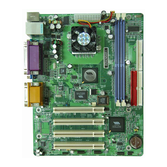
Page 6: Layout Diagram & Jumper Setting
1-3 Layout Diagram & Jumper Setting PRINT GAME/MIDI PORT PS/2 MOUSE PS/2 Keyboard COM1 LINE-IN LINE-OUT VIA VT1622A Chip K/B Power ON Jumper ATX Power Connector (JP1) CPU FAN PS2 KB/Mouse Port USB Port/ LAN Connector VIA C3 EBGA CPU DIMM Socket X2 COM2 Connector TV OUT Connector... - Page 7 Jumpers Jumper Name Description Page Keyboard Power ON Function Setting 3-pin Block USB Power On Function Setting 3-pin Block CMOS RAM Clear Function Setting 3-pin Block On board Sound Chip Enabled/Disabled 3-pin Block (for V626EMWxxx/V626EMPxxx) Connectors Connector Name Description Page ATXPWR ATX Power Connector 20-pin Block...
-
Page 8: Chapter 2 Hardware Installation
Chapter 2 Hardware installation 2-1 Hardware installation Steps Before using your computer, you had better complete the following steps: 1. Check motherboard jumper setting 2. Install CPU and Fan 3. Install System Memory (DIMM) 4. Install Expansion cards 5. Connect IDE and Floppy cables, Front Panel /Back Panel cable 6. - Page 9 (3) CMOS RAM Clear (3-pin): JP6 A battery must be used to retain the motherboard configuration in CMOS RAM short 1-2 pins of JP6 to store the CMOS data. To clear the CMOS, follow the procedure below: Turn off the system and unplug the AC power Remove ATX power cable from ATX power connector Locate JP6 and short pins 2-3 for a few seconds Return JP6 to its normal setting by shorting pins 1-2...
-
Page 10: Glossary
2-3 Glossary Chipset (core logic) - two or more integrated circuits which control the interfaces between the system processor, RAM, I/O devises, and adapter cards. Processor socket - the socket used to mount the system processor on the motherboard. Slot (AGP, PCI, ISA, RAM) - the slots used to mount adapter cards and system RAM. AGP - Accelerated Graphics Port - a high speed interface for video cards;... -
Page 11: Setting Cpu Bus Clock & Memory Clock Jumper
2-3-1 Setting CPU Bus Clock & Memory Clock Jumper Setting the front side bus frequency and SDRAM frequency The motherboard uses jumper less function for the front side bus frequency and SDRAM frequency users don’t need setting any jumper when plug the CPU in motherboard For experience user looking for over clocking possibility, please refer to sec 2-3-2. -
Page 12: Install Memory
2-4 Install Memory This motherboard provides 184-pin DUAL INLINE MEMORY MODULES (DIMM) sites for memory expansion available from minimum memory size of 64MB to maximum memory size of 2.0GB DDR SDRAM. Valid Memory Configurations Bank 184-Pin DIMM Total Memory Bank 0, 1 (DDR1) DDR200/DDR266 64MB∼1.0GB DDR SDRAM Module... -
Page 13: Expansion Cards
2-5 Expansion Cards WARNING! Turn off your power when adding or removing expansion cards or other system components. Failure to do so may cause severe damage to both your motherboard and expansion cards. 2-5-1 Procedure For Expansion Card Installation 1. Read the documentation for your expansion card and make any necessary hardware or software setting for your expansion card such as jumpers. -
Page 14: Interrupt Request Table For This Motherboard
2-5-3 Interrupt Request Table For This Motherboard Interrupt request are shared as shown the table below: INT A INT B INT C INT D INT E INT F INT G INT H √ Slot 1 √ Slot2 √ Slot3 √ Slot4 √... - Page 15 USB Port connector: UL_B1 The connectors are 4-pins connector that connect USB devices to the system board. LAN Port Connector: LAN These connectors are standard RJ45 connector for Network supports 10/100 BASE-T transfer rate. Parallel Port Connector (25-pin female): LPT Parallel Port connector is a 25-pin D-Subminiature Receptacle connector.
- Page 16 Pin 1 Floppy Drive Connector (10) Primary IDE Connector (40-pin block): IDE1 This connector supports the provided IDE hard disk ribbon cable. After connecting the single plug end to motherboard, connect the two plugs at other end to your hard disk(s). If you install two hard disks, you must configure the second drive to Slave mode by setting its jumpers accordingly.
-
Page 17: Headers
2-6-2 Headers COM2 Serial Port Headers (9-pin) : COM2 This board has one serial port header COM2, it come with cable providing serial port COM2. The On-board serial port can be disabled through BIOS SETUP. Please refer to Chapter 3 “INTEGRATED PERIPHERALS SETUP“ section for more detail information. Note: Orient the read marking on the COM2 COM2 ribbon cable to pin 1... - Page 18 USB Port Headers (10-pin) : USB1/USB2 These headers are used for connecting the additional USB port plug. By attaching an option USB cable, your can be provided with two additional USB plugs affixed to the back panel. USB1/USB2 Pin 1 USB Port Headers IDE Activity LED: HD_LED This connector connects to the hard disk activity indicator light on the case.
- Page 19 (10) FAN Speed Headers (3-pin) : CPUFAN, SFAN These connectors support cooling fans of 350mA (4.2 Watts) or less, depending on the fan manufacturer, the wire and plug may be different. The red wire should be positive, while the black should be ground. Connect the fan’s plug to the board taking into consideration the polarity of connector.
-
Page 20: Starting Up Your Computer
2-7 Starting Up Your Computer 1. After all connections are made, close your computer case cover. 2. Be sure all the switch are off, and check that the power supply input voltage is set to proper position, usually in-put voltage is 220V∼240V or 110V∼120V depending on your country’s voltage used. -
Page 21: Chapter 3 Introducing Bios
Chapter 3 Introducing BIOS The BIOS is a program located on a Flash Memory on the motherboard. This program is a bridge between motherboard and operating system. When you start the computer, the BIOS program gain control. The BIOS first operates an auto-diagnostic test called POST (power on self test) for all the necessary hardware, it detects the entire hardware device and configures the parameters of the hardware synchronization. -
Page 22: Getting Help
3-2 Getting Help Main Menu The on-line description of the highlighted setup function is displayed at the bottom of the screen. Status Page Setup Menu/Option Page Setup Menu Press F1 to pop up a small help window that describes the appropriate keys to use and the possible selections for the highlighted item. - Page 23 Standard CMOS Features Use this Menu for basic system configurations. Advanced BIOS Features Use this menu to set the Advanced Features available on your system. Advanced Chipset Features Use this menu to change the values in the chipset registers and optimize your system’s performance.
-
Page 24: Standard Cmos Features
3-4 Standard CMOS Features The items in Standard CMOS Setup Menu are divided into several categories. Each category includes no, one or more than one setup items. Use the arrow keys to highlight the item and then use the <PgUp> or <PgDn> keys to select the value you want in each item. Phoenix –... -
Page 25: Advanced Bios Features
3-5 Advanced BIOS Features Phoenix – AwardBIOS CMOS Setup Utility Advanced BIOS Features Virus Warning Disabled Item Help CPU L2 Cache ECC Checking Disabled CPU L1 Cache Enabled CPU L2 Cache Enabled Menu Level > Quick Power On Self Test Enabled First Boot Device Floppy... - Page 26 Quick Power On Self-Test This category speeds up Power On Self Test (POST) after you power on the computer. If this is set to Enabled. BIOS will shorten or skip some check items during POST. Enabled (default) Enable quick POST Disabled Normal POST First/Second/Third/Fourth Boot Device...
-
Page 27: Advanced Chipset Features
3-6 Advanced Chipset Features The Advanced Chipset Features Setup option is used to change the values of the chipset registers. These registers control most of the system options in the computer. Phoenix – AwardBIOS CMOS Setup Utility Advanced Chipset Features DRAM Timing Setting Press Enter Item Help... -
Page 28: Dram Timing Setting
3-6-1 DRAM Timing Setting Phoenix – AwardBIOS CMOS Setup Utility DRAM Timing Setting DRAM Timing By SPD Item Help x DRAM CAS Latency Bank Interleave 4 Banks RAS Precharge Time Menu Level >> RAS Active Time RAS to CAS Delay DRAM Command Rate ↑↓→←... -
Page 29: Agp Timing Settings
3-6-2 AGP Timing Settings Phoenix – AwardBIOS CMOS Setup Utility AGP Timing Settings AGP Aperture Size 64MB Item Help AGP Mode AGP Fast Write Disabled AGP Master 1 WS Write Disabled Menu Level >> AGP Master 1 WS Read Disabled CPU to AGP Post Write Enabled AGP Delay Transaction... -
Page 30: Onchip Ide Function
OnChip IDE Function Please refer to section 3-7-1 OnChip Device Function Please refer to section 3-7-2 OnChip SIO Function Please refer to section 3-7-3 Init Display First This item allows you to decide to activate whether PCI Slot or on-chip VGA first. The settings are: PCI Slot, AGP Slot, On-Chip VGA. -
Page 31: Onchip Device Function
Primary/Secondary Master/Slave UDMA Ultra DMA/33 implementation is possible only if your IDE hard drive supports it and the operating environment includes a DMA driver (Windows 95 OSR2 or a third-party IDE bus master driver). If your hard drive and your system software both support Ultra DMA/33 and Ultra DMA/66, select Auto to enable BIOS support. -
Page 32: Onboard Super Io Function
3-7-3 Onboard Super IO Function Phoenix – AwardBIOS CMOS Setup Utility Onboard Super IO Function Onboard FDD Controller Enabled Item Help Onboard Serial Port 1 3F8/IRQ4 Onboard Serial Port 2 2F8/IRQ3 Onboard Fast IR Disabled Menu Level >> Fast IR IRQ Fast IR DMA Onboard Parallel Port 378/IRQ7... -
Page 33: Power Management Setup
3-8 Power Management Setup The Power Management Setup allows you to configure your system to most effectively save energy saving while operating in a manner consistent with your own style of computer use. Phoenix – AwardBIOS CMOS Setup Utility Power Management Setup ACPI Function Enabled... -
Page 34: Wake Up Events
3-8-1 Wake Up Events Phoenix – AwardBIOS CMOS Setup Utility Wake Up Events Item Help LPT&COM LPT/COM HDD&FDD PCI Master Menu Level >> Wake-Up on Ring/LAN Disabled Wake-Up on PCI PME Disabled PS2KB Wakeup Selection Hot Key PS2KB Wakeup from S1-S5 Disabled Wake-Up on RTC Alarm Disabled... -
Page 35: Pnp/Pci Configuration Setup
3-9 PnP/PCI Configuration Setup This section describes configuring the PCI bus system. PCI, or Personal Computer Interconnect, is a system which allows I/O devices to operate at speeds nearing the speed the CPU itself uses when communicating with its own special components. This section covers some very technical items and it is strongly recommended that only experienced users should make any changes to the default settings. -
Page 36: Pc Health Status
3-10 PC Health Status This section shows the Status of you CPU, Fan, Warning for overall system status. This is only available if there is Hardware Monitor onboard. Phoenix – AwardBIOS CMOS Setup Utility PC Health Status 49 ° C Item Help Current CPU Temp 35 °... -
Page 37: Load Standard/Optimized Defaults
3-12 Load Standard/Optimized Defaults Load Standard Defaults When you press <Enter> on this item, you get confirmation dialog box with a message similar Load Standard Defaults (Y/N)? N Pressing <Y> loads the BIOS default values for the most stable, minimal-performance system operations. -
Page 38: Chapter 4 Driver & Free Program Installation
Chapter 4 DRIVER & FREE PROGRAM INSTALLATION Check your package and there is A MAGIC INSTALL CD included. This CD consists of all DRIVERS you need and some free application programs and utility programs. In addition, this CD also include an auto detect software which can tell you which hardware is installed, and which DRIVERS needed so that your system can function properly. -
Page 39: Via 4 In 1 Install Via Service Pack 4 In 1 Driver
4-1 VIA 4 IN 1 Install VIA Service Pack 4 IN 1 Driver * The path of the file is X:\VIA\DRIVER\VIAHYPERION4IN1456V.EXE IDE : VIA ATAPI VENDOR SUPPORT DRIVER IS USED TO FIXED COMPATIBILITY ISSUE FOR IDE DEVICES AGPVXD : VIA AGPVXD DRIVER IS TO BE INSTALLED, IF YOU ARE USING AN AGP VGA CARD, VIAGART.VXD WILL PROVIDE SERVICE ROUTINES TO YOUR VGA DRIVER AND INTERFACE DIRECTLY TO HARDWARE, PROVIDING FAST GRAPHIC ACCESS... -
Page 40: Vga Install Via Vga Driver
5. Click NEXT to Install ATAPI Vender 6. Click OK and Restart your computer Support Driver 4-2 VGA install VIA CLE266 VGA Driver For WINDOWS 9X/ME/NT4.0/2000/XP 1. Click VGA when MAGIC INSTALL MENU Click NEXT When ProSavageDDR Driver appears Install Setup Wizard Appears 3. -
Page 41: Sound Install Alc/Cmi Audio Driver
4-3 SOUND install ALC AC97’ Codec Audio Driver (for 626EMPxxx/626EMWxxx only ) 1. Click SOUND when MAGIC INSTALL 2. Click NEXT when the realtek AC97 Audio MENU appears Setup windows appear 3. Click Finish and Restart Windows 4. Realtek AVRACK utility 5. - Page 42 4-3-1 Sound Install CMI8738-6CH/C3DX PCI Audio Driver (for V626EMPxxx/V626EMWxxx) 1. Click SOUND when MAGIC INSTALL 2. Click Install Device Driver and Applications MENU appears 3. Choose English when Setup Language screen 4. Click Next when copyright Issue appears, click appears and Click OK Next or choose BROWSE to change the path for the file to be store 5.
- Page 43 9. This is the C-Media Audio Rack Play table 10. Click Start\Program\PCI Audio Application\ Multi-Channel Audio Demo to test the 6CH Speaker position 11. Click C-Media Mixer\Advanced\Speakers, 12. Enable USING Xear 3D, you can select 4/6 this is the C-Media Audio speaker Speakers Xear Functions Configuration setting.
-
Page 44: Lan Install Via Lan Controller Driver
4-4 LAN Install VIA LAN Controller Driver The VIA 10/100Mb PCI Ethernet Adapter Driver path is X:\VIA\LANDRV 1. Click LAN when Magic Install Menu appear Click OK and finish LAN driver installation 4-5 USB2.0 Install VIA USB2.0 DEVICE DRIVER 1. Click USB2.0 when MAGIC INSTALL 2. -
Page 45: Pc-Cillin Install Pc-Cillin 2005 Anti-Virus Program
4-6 PC-CILLIN Install PC-CILLIN 2005 Anti-virus program 1. Click PC-CILLIN when MAGIC INSTALL 2. Please select “Install program” when the MENU appear "Trend Micro internet security" installshield wizard windows appear 3. Click NEXT and Enter your Customer 4. Please select install “FULL” function or Information, Click NEXT or choose Change install “Antivirus software”... -
Page 46: How To Disable On-Board Sound
4-7 HOW TO DISABLE ON-BOARD SOUND Enter BIOS SETUP choose INTEGRATE PERIPHERALS choose ON-CHIP DEVICE FUNCTION choose AC97 AUDIO Disable on-board sound function by press PAGE DOWN KEY to Disable 4-8 HOW TO UPDATE BIOS Before update BIOS users have to “Disable”, “Flash Part Write Protect” item which in “Miscellaneous Control”...
Need help?
Do you have a question about the 626EMP Series and is the answer not in the manual?
Questions and answers