
Subscribe to Our Youtube Channel
Related Manuals for AUSTRALIAN MONITOR KA1500


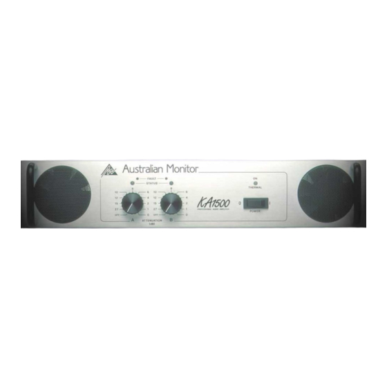
Summary of Contents for AUSTRALIAN MONITOR KA1500
- Page 1 KA1500 KA1500 KA1500 KA1500 KA1500 PROFESSIONAL AUDIO AMPLIFIER O p e r a t i o n M a n u a l...
-
Page 2: Safety Precautions
RISK OF ELECTRICAL SHOCK manual, please contact your nearest service agent or DO NOT OPEN Australian Monitor direct: The presence of an EXCLAMATION MARK contained THE TECHNICAL OFFICER within the boundaries of an equilateral triangle is... -
Page 3: Protection Features
Features: Custom designed, 2RU heavy duty alloy chassis. - 1 Watt output indication (2.828 volts). - Open modular construction for ease of servicing. - 1 dB below output clip indication. - Symmetrical layout - even weight distribution. - Massive heat-sink / heat-exchangers. - Well-regulating, high current power supply. -
Page 4: Table Of Contents
Contents Page Introduction Controls, Connectors and Indicators 2.1 Front Panel 2.2 Rear Panel Installation Operation Bridge Mode Two Ohm or Not Two Ohm Maintenance Warranty Specification List of Illustrations Page Figure 1. Block Diagram Figure 2. Front Panel Layout Figure 3. Rear Panel Layout Figure 4. -
Page 5: Introduction
-Series amplifiers are 2 unit (3.5") tall, 19" wide rack mountable units. Each channel of the amplifier comprises a balanced Congratulations on choosing Australian Monitor for active input with a buffered attenuator driving a your professional amplification requirements. differential class A drive stage which in turn drives a... -
Page 6: Controls, Connectors And Indicators
6 Controls & Connectors 2. Controls, Connectors & Indicators Figure 2 Front Panel Layout... -
Page 7: Front Panel
Controls & Connectors 7 Front Panel 3 Fault Indicator KA KA KA KA KA Series models have identical front panel layouts. This amber LED will flash when a fault condition Figure 1 shows the panel layout of the KA KA KA KA KA Series. -
Page 8: Figure 3 Rear Panel Layout
8 Controls & Connectors Figure 3 Rear Panel Layout... -
Page 9: Rear Panel
Controls & Connectors 9 Rear Panel 6 Balanced Input A female 3-pin XL type connector is provided on The wires in the mains lead are colored in each input: accordance with the following code: Pin 1 = Signal Ground; Pin 2 = Hot (non-inverting or in phase); BROWN = ACTIVE;... -
Page 10: Figure 4. Case Dimensions
10 Installation Figure 4 Dimensions... -
Page 11: Installation
When you first receive your amplifier it may not have a mains plug attached. You must ensure that an Each channel of your KA1500 amplifier is cooled by appropriate plug is used and corresponds with the twin axial fans which draw cool air from the front of amplifier’s current (ampere) requirements and meets... -
Page 12: Figure 5. "Speakon" Connector Wiring
12 Installation NOTE: In-line XLR connectors often have a When using the NEUTRIK SPEAKON (NL4MP) termination lug that connects directly to the chassis connector for speaker output, use only the mating of the connector. NEUTRIK NL4FC in-line connector. This connector Do not link this lug to pin 1 at the amplifier’s input as is designed so that both channels can be fed from a it will defeat the amplifier’s input grounding scheme. -
Page 13: Operation
Operation 13 4. Operation circuit is in operation for the first 0.5 seconds. This limits the mains current to prevent "nuisance-tripping" of circuit breakers. IMPORTANT During this period the THERMAL/ON LED will flash All signal source equipment should be adequately red whilst the mains voltage gradually charges up the earthed. - Page 14 14 Operation not present a difficult load for any signal source. equipment earth appears to the amplifier's input as a signal and is amplified as hum. Your signal source (i.e. the equipment feeding the amplifier) should have an output impedance of There are three things you can do to avoid earth loop 600 Ohms or lower to avoid unwanted high frequency problems:...
-
Page 15: Bridge Mode
A common use of an amplifier in BRIDGE mode is for pin marked 2+. driving 70 volt & 100 volt distribution lines. In BRIDGE mode, The KA1500 KA1500 can produce over 110 volts with NOTE: You should check after market manufactured... -
Page 16: Two Ohm Or Not Two Ohm
A preamble. Your amplifier is designed to be able to deliver KA1500 KA1500 KA1500 KA1500 KA1500 more than twice the current than that shown on the The load that a loudspeaker presents to an amplifier... -
Page 17: Maintenance
It is important to note that the fan blades must be held still whilst blowing air Your amplifier will need minimal maintenance. over the blades otherwise you may burn out the KA1500 KA1500 KA1500 KA1500 KA1500 No internal adjustments need to be made to the unit bearings in the fan. -
Page 18: Warranty
-SERIES 2 YEAR WARRANTY REGISTRATION IMPORTANT Please complete this card and return it immediately after unpacking the product. This card is to be sent DIRECTLY to Australian Monitor. NOTE! Warranty is effective ONLY upon receipt of this card. COMPANY NAME... -
Page 19: Specification 19
Specification 19 KA1500 Specifications KA1500 Specifications KA1500 Specifications KA1500 Specifications KA1500 Specifications Output Condition Output Power E.I.A. 1 kHz, <0.1 % THD+N. 8 ohm 4 ohm 2 ohm Single channel driven. 550W 850W 1,150W Both channels driven. 500W 750W 1,000W Pulsed @ 1 kHz, at onset of clipping, 10% duty cycle. - Page 20 www.australianmonitor.com.au Distributed by: Audio Telex Communications Pty Ltd ACN 001345482 www.audiotelex.com.au International Enquiries Ph: 612 9647 1411, Fax: 612 9748 2537, E-mail: ho@audiotelex.com.au Sydney Ph: (02) 9647 1411, Fax: (02) 9648 3698, E-mail: nsw@audiotelex.com.au Melbourne Ph: (03) 9890 7477, Fax: (03) 9890 7977, E-mail: vic@audiotelex.com.au Brisbane Ph: (07) 3852 1312, Fax: (07) 3252 1237, E-mail: qld@audiotelex.com.au Adelaide...
Need help?
Do you have a question about the KA1500 and is the answer not in the manual?
Questions and answers