Advertisement
Quick Links
Библиотека СОК
Litho U.S.A.
E2001
DIMENSIONS
. . . . . . . . . . . . . . . . . . . . . . . . . . . . . . . . . . . .
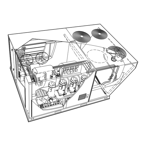
PARTS ARRANGEMENTS
SHIPPING AND PACKING LIST
GENERAL
. . . . . . . . . . . . . . . . . . . . . . . . . . . . . . . . . . . . . . . .
REQUIREMENTS
UNIT SUPPORT
. . . . . . . . . . . . . . . . . . . . . . . . . . . . . . . . . .
DUCT CONNECTION
RIGGING UNIT FOR LIFTING
CONDENSATE DRAINS
GAS PIPING
. . . . . . . . . . . . . . . . . . . . . . . . . . . . . . . . . . . . . .
04/01
*2P0401*
. . . . . . . . . . . . . . . . . . . . . . . . .
. . . . . . . . . . . . . . . . . . . . .
. . . . . . . . . . . . . . . . . . . . . . . . . . . . . . . . .
. . . . . . . . . . . . . . . . . . . . . . . . . . . . . .
. . . . . . . . . . . . . . . . . . . . . .
. . . . . . . . . . . . . . . . . . . . . . . . . . .
INSTALLATION
INSTRUCTIONS
504,351M
4/2001
Supersedes 10/2000
1
PRESSURE TEST GAS PIPING
2
HIGH ALTITUDE DERATE
3
FACTORY-INSTALLED OPTIONS
3
ELECTRICAL CONNECTIONS
3
BLOWER OPERATION AND ADJUSTMENTS
3
COOLING START-UP
. . . . . . . . . . . . . . . . . . . . . . . . . . . . . .
4
GAS HEAT START-UP
4
HEATING OPERATION AND ADJUSTMENTS
5
ELECTRIC HEAT START-UP
5
SERVICE
. . . . . . . . . . . . . . . . . . . . . . . . . . . . . . . . . . . . . . . .
LGA240 SHOWN
. . . . . . . . . . . . . . . . . . . .
. . . . . . . . . . . . . . . . . . . . . . . . . .
. . . . . . . . . . . . . . . . . . .
. . . . . . . . . . . . . . . . . . . . .
. . . . . . . .
. . . . . . . . . . . . . . . . . . . . . . . . . . . . .
. . . . . . . .
. . . . . . . . . . . . . . . . . . . . . . .
504,351M
*P504351M*
6
6
6
7
8
12
16
17
17
18
Advertisement

Related Manuals for Lennox LCA180


Summary of Contents for Lennox LCA180
- Page 1 Библиотека СОК INSTALLATION INSTRUCTIONS Litho U.S.A. E2001 504,351M 4/2001 Supersedes 10/2000 DIMENSIONS ........PRESSURE TEST GAS PIPING .
- Page 2 Note: All options shown; see Engineering Handbook for standard and optional features. Page 1...
- Page 3 LGA156, 180, 210, 240, 300S PARTS ARRANGEMENT (Factory-installed option) LCA156, 180, 210, 240, 300S PARTS ARRANGEMENT (Factory-installed option) Page 2...
- Page 4 Ç Ç Ç Ç Ç Ç Ç Ç Ç Ç Ç Ç Ç Ç 1- Assembled unit Check unit for shipping damage. Receiving party should Ç Ç Ç Ç Ç Ç Ç Ç Ç Ç Ç Ç Ç Ç Ç contact last carrier immediately if shipping damage is found.
- Page 5 3- Frame or supports must be high enough to prevent form moisture from entering unit. Rig unit for lifting by attaching four cables to holes in unit Recommended minimum frame height is 14" base rail. See figure 2. (356mm). 1- Detach wooden base protection before rigging. 4- Duct must be attached to the roof mounting frame and not to the unit.
- Page 6 Make drain connection to the 1" N.P.T. drain coupling provided on unit. A trap must be installed between drain connection and an open vent for proper condensate removal. See figure 3. It is sometimes acceptable to drain condensate onto the roof or grade; however, a tee should be fitted to the trap to direct condensate downward.
- Page 7 Units may be installed at altitudes up to 2000 feet (610 m) When pressure testing gas lines, the gas valve must be above sea level without any modification. At altitudes disconnected and isolated. Gas valves can be damaged if above 2000 feet (610 m), units must be derated to match subjected to more than 0.5 psig (3.48kPa).
- Page 8 Do not apply power or close disconnect switch until installation is complete. Refer to start-up directions. Refer closely to unit wiring diagram. Refer to unit nameplate for minimum circuit ampacity and maximum fuse size. 1- 230/460/575 volt units are factory wired. For 208V supply, disconnect the orange wire (230V) at control power transformer(s).
- Page 9 Locate thermostat approximately 5 feet (1524mm) above the floor in an area with good air circulation at average temperature. Avoid locating the room JUMPER TERMINALS 8 & 9 thermostat where it might be affected by: WHEN THERMOSTAT HAS NO NIGHT SETBACK TERMINALS -drafts or dead spots behind doors and in corners -hot or cold air from ducts -radiant heat from sun or appliances...
- Page 10 LOOSEN ALLEN SCREW & 1-Loosen four screws securing blower motor to TURN PULLEY CLOCKWISE sliding base. 2-Turn adjusting screw to the left, or counter TURN PULLEY clockwise, to move the motor downward and COUNTERCLOCKWISE tighten the belt. 3-Tighten four screws. 1- Loosen four screws securing blower motor to sliding force below...
- Page 11 determine the drive number and table 5 to determine the For field-furnished blower drives, use tables 2 and 3 to manufacturer's model number. determine BHP and RPM required. Reference table 4 to TABLE 2 D-LCA156H units require 5200 cfm (2455 L/s) minimum air with electric heat.
- Page 12 3500 1650 .03 (7) .03 (7) .01 (2) .04 (10) .05 (12) 3750 1770 .03 (7) .04 (10) .01 (2) .04 (10) .06 (15) 4000 1890 .04 (10) .04 (10) .01 (2) .05 (12) .06 (15) 4250 2005 .04 (10) .04 (10) .01 (2) .05 (12)
- Page 13 BROWNING NO. OEM PART NO. BROWNING NO. OEM PART NO. BROWNING NO. OEM PART NO. 1VP40x7/8 79J0301 1BK95X1-7/16 80K1601 BX59 59A5001 1VP50x7/8 P-8-2187 BK100x1 7/16 39L1301 BX62 57A7701 1VP50x1-1/8 P-8-1977 BK100x1 7/16 39L1301 BX62 57A7701 2VP65x1-1/8 97J6001 2BK110x1 7/16 P-8-5123 BX66 97J5901 2VP60x1-1/8...
- Page 14 Page 13...
- Page 15 This unit is factory charged and should require no further adjustment. If the system requires charge, reclaim the charge, evacuate the system, and add required nameplate charge. NOTE - System charging is not recommended below 60°F (15°C). In temperatures below 60°F (15°C) , the charge must be weighed into the system.
- Page 16 See unit wiring diagram to determine which controls are used on each unit. 1- High Pressure Switch (S4, S7, S28, S96) The compressor circuit is protected by a high pressure switch which cuts out at 410 psig + 10 psig (2825 kPa + 70 kPa) and automatically resets at 300 psig + 20 psig (2069kPa + 138kPa).
- Page 17 LGA/LCA210, 240 & 300S Condenser fans 1 and 2 are energized on a Y1 cooling demand. An increased Y2 demand will energize condenser fans 3 and 4. The C1 (A56) controller de-energizes condenser fan 2 and the C2 (A59) controller de-energizes condenser fan 4 when outdoor temperature drops BEFORE LIGHTING smell all around the appliance area below 55°F (13°C).
- Page 18 1- If using an electromechanical thermostat, set to the lowest setting. 2- Before performing any service, turn off all electrical power to the appliance. 3- Open or remove the heat section access panel. 4- Turn the knob on the gas valve clockwise .
- Page 19 The unit should be inspected once a year by a qualified service technician. Units are equipped with six 24 X 24 X 2" filters. Filters should be checked and replaced when necessary with filters of like kind and size. Take note of air flow direction marking on filter frame when reinstalling filters.
- Page 20 c- Remove burner retaining bracket and lift burners from orifices. d-Clean as necessary and replace burners. Refit retaining brackets. Make sure that burner heads line up correctly. Spark gap on ignition electrode must be properly set. Refer to Heating Adjustment section. Replace access panel.
Need help?
Do you have a question about the LCA180 and is the answer not in the manual?
Questions and answers