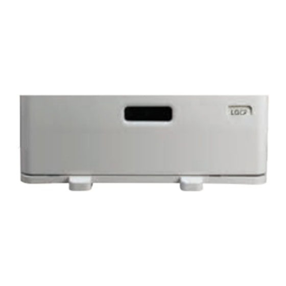
Summarization of Contents
Unit Overview
Front Sectional View
Provides a detailed sectional view of the feeder unit's front components and their arrangement.
Layout of Electrical Parts
Illustrates the physical placement of various electrical components and sensors within the feeder unit.
Electrical Components
Lists and describes the function of motors, clutches, sensors, switches, and the PC board used in the unit.
General Operation and Functionality
Configuration and Drive System
Explains the main components of the feeder and the drive systems that control their movement.
Description of Operation
Details the operational sequence from power-on to paper feeding during copying.
Error Detection and Handling
Describes common paper jams and sensor-related errors, including call-for-service conditions.
Disassembly and Component Replacement
Installation and Removal of Covers
Step-by-step instructions for removing various covers to access internal components.
LCF Board (PWA) Replacement
Procedure for removing and replacing the Main Logic Control Feeder (LCF) Printed Circuit Board Assembly.
Feeding Unit Removal
Steps to remove the main feeding unit assembly for maintenance or replacement.
Feed, Pickup, and Separation Rollers
Instructions for removing and replacing the key rollers responsible for paper feeding and separation.
Motor Replacement
Procedures for removing and replacing the LCF transport motor, tray-up motor, and end fence motor.
Feed Clutch (CLT1) Replacement
Steps for removing and replacing the feed clutch component responsible for driving the feed rollers.
Sensor Replacement
Guides for removing and replacing various sensors critical for paper detection and movement.
Switch Replacement
Procedures for removing and replacing switches used for detecting cover status and drawer presence.
Electric Circuit Diagrams
Harness Diagram
Visual representation of the wiring connections between components and the control board.
Circuit Diagram Details
Detailed schematics showing the electronic components and their interconnections.
PC Board Layout
Diagram illustrating the physical layout and component placement on the main PC board.


Need help?
Do you have a question about the KD-1059 and is the answer not in the manual?
Questions and answers