Table of Contents
Advertisement
Quick Links
Advertisement
Table of Contents

Related Manuals for IFM LK3123


Summarization of Contents
Preliminary Note and Safety Instructions
Symbols Used
Lists symbols used in the document, including instructions, reactions, and cross-references.
Safety Instructions
Outlines responsibilities for system safety and general safety precautions for the product.
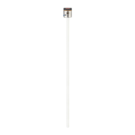
Functions and Features
Application Area
Details the intended use of the unit, particularly in machine tool building.
Restriction of the Application Area
Lists media and applications for which the unit is not suitable.
Getting Started
Example Configuration 1
Details a specific setup for mineral oil with overflow prevention, including distances and parameter settings.
Example Configuration 2
Describes a setup for coolant emulsion with automatic medium detection, including distances and parameter settings.
Function and Operating Principle
Measuring Principle
Describes how the sensor determines level using the capacitive measuring principle and active segments.
Operating Principle / Features of the Unit
Explains the unit's installation, outputs, and the different operating modes available.
Operating Modes
Details three operating modes: manual with overflow prevention, manual without, and automatic detection.
Notes on the Integrated Overflow Prevention
Provides detailed information and operational notes regarding the integrated overflow prevention feature.
Display Functions
Explains how the unit displays the current level and switching status via LEDs and alphanumeric display.
Analogue Functions
Describes the analogue output (OUT2) and its configuration options.
Curve of the Analogue Signal with Overflow Prevention
Illustrates the analogue signal output behaviour when overflow prevention is activated.
Curve of the Analogue Signal Without Overflow Prevention
Illustrates the analogue signal output behaviour when overflow prevention is deactivated.
Switching Functions
Explains the selectable switching functions for the switching output (OUT1).
Offset for Indicating the Real Level in the Tank
Describes how to set an offset value to refer switch points to the actual tank bottom.
Defined State in Case of a Fault
Explains how outputs behave when a fault is detected or signal quality is low.
IO-Link
Details the IO-Link interface capabilities for data access and parameter setting.
Installation Guidelines
Installation Instructions for Operation with Overflow Prevention
Gives specific instructions for installing the unit when overflow prevention is active.
Installation Instructions for Operation Without Overflow Prevention
Details installation procedures when overflow prevention is deactivated.
Installation in the Inactive Zone
Explains how to install the sensor within the inactive zone of the tank.
Installation in the Active Zone
Provides instructions for installing the sensor within the active zone of the tank.
Other Installation Notes
Covers additional installation considerations for different pipe types and marking installation height.
Marking of the Installation Height
Explains the use of a tube clip to ensure correct and reproducible sensor installation height.
Menu Structure and Parameter Setting
Menu Structure
Visual representation of the parameter menu structure and item dependencies.
Parameter Setting in General
Step-by-step guide on entering and confirming parameter values using the buttons.
Basic Settings
Covers essential initial parameter settings like unit of measurement, offset, and medium selection.
Set Unit of Measurement [uni]
Instructions on selecting the unit of measurement (cm or inches) for the display.
Set Offset [OFS]
Guide to setting the offset value, which defines the reference point for level measurement.
Set Medium [MEdI]
Instructions for matching the sensor's sensitivity to the specific medium being measured.
Set Overflow Prevention [OP]
How to define and set the overflow prevention point, or deactivate it.
Adjust Overflow Prevention [cOP]
Procedure for adjusting the overflow prevention OP after installation or parameter changes.
Set Output Signals
Configuration of the switching and analogue outputs according to application needs.
Set Output Function [ou1] for OUT1 (Switching Output)
How to configure the switching output for hysteresis or window functions.
Set Output Function [ou2] for OUT2 (Analogue Output)
Options for configuring the analogue output as current or voltage signals.
Define Switching Limits [SP1] / [rp1] (Hysteresis Function)
Setting the ON and OFF points for the hysteresis switching function.
Define Switching Limits [FH1] / [FL1] (Window Function)
Setting the upper and lower limits for the window switching function.
Set Switching Delay [dS1] for the Switching Output
Setting a delay time for the switching output signal.
Set Switch-Off Delay [dr1] for Switching Output
Setting a delay time for when the switching output turns OFF.
Define Switching Logic [P-n] for the Switching Output
Selecting the output logic (PNP or NPN) for the switching output.
Define Response of the Outputs in Case of a Fault [FOUx]
Configuring how outputs behave during a fault condition.
Configure Display [diS]
Options to enable or disable the alphanumeric display to save power.
Reset All Parameters to Factory Settings [rES]
Procedure for restoring the unit to its default factory settings.
Operation and Error Indication
Operation Indication
Explains the different display messages and LED indicators during operation and initialization.
Read Set Parameters
How to view the currently set parameters on the unit's display.
Error Indications
Lists possible causes and recommended measures for different error codes shown by the unit.
Output Response in Different Operating States
Table showing how OUT1 and OUT2 behave during initialization, fault, and normal operation.
Technical Data and Calculations
Setting Values [OFS]
Table showing the setting range and step increment for the offset parameter.
Setting Values [OP]
Table listing the available setting values for the overflow prevention parameter (OP) for different models.
Calculation Aids [OP]
Formulas and examples to help calculate the correct overflow prevention (OP) setting.
Definition "from the cover"
Explains how to calculate the OP value based on measurements from the tank cover.
Definition "from the bottom"
Explains how to calculate the OP value based on measurements from the tank bottom.
Setting Ranges Switching Limits for Level
Tables showing the setting ranges and step increments for switching limits (SP1/FH1, rP1/FL1).
Maintenance and Factory Settings
Maintenance / Cleaning / Change of Medium
Guidelines for performing maintenance, cleaning, or changing the medium.
Maintenance Information for Operation Without Overflow Prevention
Specific reinitialization requirements after maintenance or changes when overflow prevention is off.
Factory Setting
A table summarizing the default factory settings for various parameters across different models.
Need help?
Do you have a question about the LK3123 and is the answer not in the manual?
Questions and answers