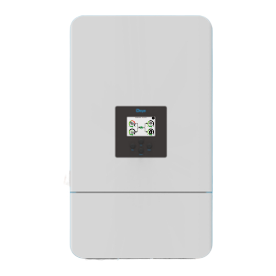
Table of Contents
Advertisement
Quick Links
Advertisement
Table of Contents

Summarization of Contents
Safety Introductions
Labels Description
Details safety symbols used on the inverter and their meanings.
Product Information
Product Overview
Provides a detailed overview of the inverter's components and ports.
Product Size
Shows the physical dimensions and measurements of the inverter.
Product Features
Lists the key features and capabilities of the hybrid inverter.
Basic System Architecture
Illustrates the inverter's role within a solar power system.
Installation and Wiring
Parts List
Lists all the components included in the inverter package.
Product Handling Requirements
Guidelines for safely lifting and transporting the inverter unit.
Mounting Instructions
Instructions and precautions for securely mounting the inverter on a wall.
Battery Connection
Detailed procedures and requirements for connecting the battery to the inverter.
Grid and Backup Load Connection
Steps for connecting the inverter to the grid and backup load terminals.
PV Connection
Instructions for connecting solar PV modules to the inverter.
CT Connection
Guide for connecting current transformers (CTs) for power monitoring.
Meter Connection
Instructions for connecting external energy meters to the inverter.
Earth Connection
Mandatory procedure for grounding the inverter for safety.
WIFI Connection
Steps for configuring the optional Wi-Fi connection for monitoring.
Wiring System Overview
Diagram illustrating the overall wiring system for the inverter.
Wiring Diagrams
Detailed wiring diagrams for different system configurations and connections.
Generator Connection Diagram
Diagram showing how to integrate a diesel generator with the inverter.
Parallel Connection Diagram
Diagram for connecting multiple inverters in parallel for increased capacity.
Operation
Power ON/OFF
Instructions on how to turn the inverter on and off safely.
Operation and Display Panel
Explanation of the inverter's front panel controls and LCD display.
LCD Display and System Setup
Main Screen Overview
Overview of the main screen interface, icons, and system status indicators.
LCD Operation Flow Chart
Visual flow chart of navigating the inverter's LCD menu system.
Solar Power Curves
Details on viewing solar power generation curves over time.
Battery Status and Curves
Displays detailed battery information and generation/consumption curves.
System Setup Menu
Access point to various system configuration menus.
Basic Setup Menu
Menu for configuring fundamental inverter settings like time and dimming.
Battery Setup Menu
Configuration options for battery type, capacity, and charging settings.
Generator and Battery Settings
Detailed settings for generator use and battery parameters.
System Work Mode Setup
Setting up various operational modes like Selling First, Zero Export, etc.
Grid Setup Menu
Menu for configuring grid code, frequency, voltage, and protection settings.
Generator Port and Advanced Functions
Setup for generator port use and advanced inverter features.
Device Information
Accessing inverter ID, firmware versions, and alarm codes.
Operational Modes
Basic Mode
Overview of the basic operational mode of the inverter.
Generator Mode
Diagram illustrating operation with a connected generator.
Smart-Load Mode
Diagram showing operation with a smart load connected.
AC Couple Mode
Diagram illustrating the AC couple operation mode.
Appendix I: Port Pin Definitions
RJ45 Port Pin for BMS
Pinout configuration for the BMS communication port (RJ45).
RJ45 Port Pin for Meter-485
Pinout configuration for the Meter-485 communication port (RJ45).
RJ45 Port Pin for Modbus
Pinout configuration for the Modbus port (RJ45) for remote monitoring.
RJ45 Port Pin for DRM
Pinout configuration for the DRM (Demand Response Mode) port (RJ45).
Appendix II: Component Dimensions
Split Core Current Transformer (CT) Dimensions
Detailed dimensions for the split core current transformer accessory.


Need help?
Do you have a question about the SUN-12K-SG05LP3-EU-SM2 and is the answer not in the manual?
Questions and answers