Deye SUN-12K-G03 User Manual
Grid-tied pv string inverter
Hide thumbs
Also See for SUN-12K-G03:
- User manual (58 pages) ,
- User manual (51 pages) ,
- User manual (62 pages)
Table of Contents
Advertisement
Advertisement
Table of Contents

Related Manuals for Deye SUN-12K-G03


Summary of Contents for Deye SUN-12K-G03
- Page 1 Grid-tied PV String Inverter User Manual...
- Page 2 1. Introduction - 01 - ………………………………………………………… 1.1 Appearance Introduction - 01 - ………………………………………… 1.2 Parts list - 01 - ………………………………………………………… 2. Safety warnings and instructions - 02 - ……………………………………… 2.1 Safety signs - 02 - ………………………………………………………… 2.2 Safety instructions - 03 - …………………………………………………...
-
Page 3: Appearance Introduction
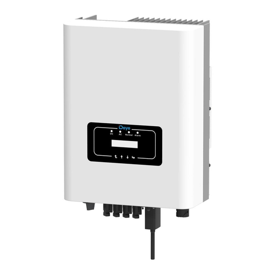
1.1 Appearance Introduction Three Phase String Power Inverter can convert solar panel DC power into AC power which can directly input to the grid. Its appearance is shown below.These models contain SUN-12K-G03、SUN-15K-G03、SUN-18K-G03. The following is collectively referred to as‘inverter’. Normal Alarm Pic1.1 Front view... -
Page 4: Safety Warnings And Instructions
Pic1.3 Accessories drawing Description Grid-tied PV String Inverter Wall mounting bracket Mounting stainless steel screws M4×12 AC power connectors DC power connectors(including Inserted spring) 2pairs Stainless steel Collision bolt M6×80 User manual Wifi-Plug(optional) Square hole sealing plate(Wi-Fi Function selection) 1.1 Parts list 2. -
Page 5: Shock Hazard
Warning: Safety warning——Indifference of the signs in the manual may cause injury or even death. Shock Hazard: Shock warning sign——Incorrect follow of this sign may get shocked. Safety Hint: Prudent operation——Incorrect follow of the safety operation hints in this manual may cause inverter defective. High Temperature Hazard:... - Page 6 Shock Hazard: When PV module is exposed to sunlight, The output will generate DC voltage.Prohibit touching to avoid shock hazard. Shock Hazard: After disconnecting the input and output of the inverter,it takes at least 5 minutes for the inverter to completely release the residual energy and wait for at least 5 minutes before it can be overhauled.
-
Page 7: Operation Interface
7. When starting the inverter, first close the closed-circuit grid-side switch and close the DC input terminal; when closing the inverter, disconnect the grid-side switch first and then disconnect the DC-side switch. 8. Don’t insert and remove AC and DC terminals when the inverter is in normal operation. -
Page 8: Lcd Display
Indicator status Explanation Inverter detects DC input ●DC Low DC input voltage Grid Connected ●AC Grid Unavailable Under normal operating ● NORMAL Stop operating Detected faults or report faults ● ALARM Under normal operating 3.3 Buttons There are four buttons on the inverter panel:above is up and increase button (UP), below is down and decrease button (DOWN), left is ESC button (ESC), right is Enter button (ENTER). -
Page 9: Product Installation
4. Product installation 4.1 Select installation location After receiving the inverter and preparing to install it, please select a suitable location, should consider below factors: ● Ventilation—Must insure the air ventilation of the installation location, improper installation may cause overheating and effect the working efficiency and lifespan. ●... -
Page 10: Safety Hints
● Please select the wall with certain bearing capacity. ● When doing the installation, vertical slope cannot exceed +/-15°.Make sure no lateral tilt. Otherwise it will affect the function of the heat sink. Cause the output power lower than expected. ●... -
Page 11: Inverter Installation
≥500mm ≥500mm Pic4.3 Installation Gap 4.2 Inverter Installation The inverter is designed according to the wall mounted type installation, please use the wall mounted (the brick wall of the expansion bolt) when installing. Anchoring Mounting bracket M4*14 Stainless steel screws Inverter Pic4.4 Inverter Installation - 09 -... - Page 12 Inverter should be vertically installed, as shown in pic 4.5,installation procedure show below: 1. Position the bolts on the appropriate wall according to the bolt positions on the mounting shelves and mark the holes. On the brick wall, the installation must be suitable for the expansion bolt installation.
-
Page 13: Electrical Connection
Pic4.6 Mounting of inverter 5 Electrical Connection The inverter has considered the convenience of the electrical connection while designing. we design fast connection for both DC and AC ,all electrical connections conform to the related standards of the country . 5.1 DC input terminal connection In order to safe connection, the electrical connection must follow below steps:... - Page 14 a). Make sure that the polarity of the output voltage of the solar panel is consistent with the polarity identified by the inverter. b). Connect DC positive and negative to the inverter input terminal. Figure 5.1 is shown in figure 5.2. Pic 5.1 DC “+ ”connector (MC4) Pic 5.2 DC“-”connector (MC4) c).Making DC connection line Strip off the DC wire about 7mm, disassemble the...
- Page 15 2). Insert the contact pin into the connector housing until it locks in place. Screw the cap nut onto the connector housing. Torque to 2.5-3Nm(as shown in pic 5.5). Pic 5.5 connector with cap nut screwed on Traverse area(mm ) Outside diameter Cable type Recommended...
- Page 16 NOTE: Sunlight shines on the panels will generate voltage, high voltage in series may cause danger to life. Therefore, before connecting the DC input line, the solar panel needs to be blocked by the opaque material and ensure that the DC switch is 'OFF', otherwise, the high voltage of the inverter may lead to life-threatening conditions.
- Page 17 1. Matching socket 2.Sleeve 3.Sealing core 4.Sealing nut Pic 5.7 AC connector structure The AC output connector is divided into three parts: matching socket, sleeve and sealing sleeve, as shown in Picture 5.7, the steps are as follows: Step 1 Remove the cable sealing ring and sleeve in sequence from the AC connector. Step 2 Use strippers to strip the protective sheath and insulation layer of the AC cable to the right length, as shown in Picture 5.8.
- Page 18 Pic 5.9 AC Connector Hole Pattern Safety Hint: when connection please according to above picture, ensuring each cable plug into corresponding port. Step 5 Set the sleeve and sealing ring in place Step 6 Connect the terminals to the inverter as shown in picture 5.10. Pic 5.10 AC input connection - 16 -...
-
Page 19: Inverter Monitoring Connection
5.3 The connection of the ground line Good grounding is good for resisting surge voltage surge and improving EMI performance. Therefore, before connecting AC, DC, and communication cables, you need to ground the cable firstly. For a single system, just ground the PE cable; For multiple machine systems, all PE cables of the inverter need to be connected to the same grounding copper platoon to ensure the equipotential connection. - Page 20 Phone GPRS Router Web Server WIFI Pic 5.12 Internet monitoring solution 5.4.1 Installation of Wi-Fi Plug When the inverter is out of the factory, the installation location of Wifi plug is sealed by a sealed plate as shown in Figure 5.13.When installing the Wifi Plug, remove the sealing plate, replace it with the sealing plate with square hole in the accessories, and tighten the screws.
-
Page 21: Startup And Shutdown
Pic 5.13 Wifi Plug installation diagram 5.4.2 Configuration of Wi-Fi Plug For the configuration of Wi-Fi Plug,please refer to illustrations of the Wi-Fi Plug. 6. Startup and Shutdown Before starting the inverter, make sure that the inverter can meet the following conditions, otherwise it may result in fire or damage to the inverter. -
Page 22: Inverter Shutdown
6.1 Start up the inverter When start up the three phase string inverter, should fellow below steps: 1. First switch on the AC breaker. 2. Turn on the dc switch of the photovoltaic module, and if the panel provides sufficient starting voltage and power, the inverter will start. 3. - Page 23 L1(L)L1(K)L2(L)L2(K)L3(L)L3(K) Pic 7.1 Limiter view 7.1 Limiter function wiring diagram - 20 - When you are reading this, we believe that you have completed the connection according to the requirements of chapter 5, if you has been running your inverter at this time, and you want to use the limiter function, please turn off AC and DC switch of the inverter, and wait for 5 minutes until the inverter completely discharged.
- Page 24 L1(L) Solar panels L1(K) L2(L) L2(K) L3(L) L3(K) Limiter Normal Alarm Control signal Normal Alarm Distribution Box Control signal Load Pic 7.2 Wiring diagram 7.2 Connect the limiter to inverter The limiter will measure the voltage and current of three phases separately, and this manual only introduces the installation steps of one phase, the other two phases are the same.
- Page 25 Pic7.3 Clamp Senor Pic7.4 Clamp Senor internal arrow (3)After you finish the installation in process 1 and 2, connect the N line (N) to the N terminal of the limiter and tighten the line. (4)Connect the control line. There are two numbers 1 and 2 on the interface of limiter, and the same on the waterproof terminal of the inverter.
- Page 26 Pic7.7 Connect terminal to inverter 7.3 Use of anti-backflow function When the connection is completed, the following steps should be referenced to use this function: 1.Turn on the AC switch 2. Turn on the DC switch , Waiting inverter LCD lighting up 3.Press Enter button on the LCD panel in the main interface into the menu options, select [parameter setting] to Enter setup submenu, and then select [running parameters] as shown in figure 7.8,at this time please Input the default password 1234 through pressing...
- Page 27 << System Param Param Pic7.8 Parameter setting Fun GFDI OFF << Limiter Pic 7.9 Limit switch 4. Operate the button [up down], move setting cursor to limit function and press the button [enter] .At this time you can turn on or turn off the limit function by choosing [up down] button, please press [enter] button to confirm when setting done.
- Page 28 7.4 Notes while using limit function For your safety and the operation of limiter function of the inverter, we put forward the following Suggestions and precautions: Warning: In limit function we strongly recommend that the two photovoltaic arrays are formed by the same number of photovoltaic panels of the same size, which will make the inverter more responsive to limit the power.
-
Page 29: General Operation
8. General Operation During normal operation, the LCD shows the current status of the inverter,including the current power, total generation, a bar chart of power operation and inverter ID,etc. Press the Up key and the Down key to see the current DC voltage, DC current, AC voltage, AC current, inverter radiator temperature,software version number and Wifi connection state of the inverter. - Page 30 Power: 108W State: Normal Pic8.2 The initial interface Press UP or Down you can check inverter DC voltage, DC current, AC voltage, AC current, inverter temperature, software version information. PV1: 0.0V 0.0A PV2: 0.0V 0.0A Pic8.3 PV input and DC current information You can check the PV information, the number of strings input,MPPT voltage and MPPT current.
-
Page 31: Device Info
8.2 Statistics information There are five submenus in the statistics. << Device Info. Fault Record Pic8.7 Statistics Into each submenu through cursor. GL1030 SN-01 ID:1707010001 Pic8.8 E-Day ID:1707010001 Ver0201 Ver5102 Pic8.9 E-Month This information is for technician's reference. 8.3 Fault Record Only can keep four fault record in the menu include time, customer can deal with it depends on the error code. - Page 32 8.5 Parameter setting Setting includes system param, run param, protect param, comm:param. All of these information for maintenance reference. 8.5.1 System Param << System Param Param Pic8.12 Setting Param << Protect Param Protect Param << Comm. Param Pic8.13 Setting System Param includes time set, language set, display set and factory reset. Time Set <<...
- Page 33 8.5.1.1 Time set 20181017 OK 08:45:57 Cancel Pic8.15 Time set 8.5.1.2 Language set << English Pic8.16 Language set 8.5.2 Running Param Note: Password required-restricted access-authorized engineer only.Un- authorized access may avoid the warranty. The initial password is 1234. PassWord **** Pic8.17 Password <<...
- Page 34 8.5.3 Protect Param Note: Engineer Only. We will set the param depends on the safety requirements, so customers don’t need to reset it. The password is same as 8.5.2 Running param. << oo CHINA oo BRAZIL 00 EN50549 << 00 CUSTOM Pic8.19 Protect Param Note:...
-
Page 35: Repair And Maintenance
<< AC OverFreq 51.50Hz << AC LowFreq 47.50Hz Pic8.20 “CUSTOM” 9. Repair and Maintenance String type inverter doesn't need regular maintenance. However, debris or dust will affect heat sink's thermal performance. It is better to clean it with a soft brush.If the surface is too dirty and affect the reading of LCD and LED lamp, you can use wet cloth to clean it up. - Page 36 10.1 Error code In the case of failure the LCD screen will display an alarm message. In this case the inverter may stop feeding energy into the grid. The alarm description and their corresponding alarm messages are listed Table 9.1. Error code Description Solutions...
- Page 37 Error code Description Solutions 1. Measure the actual grid voltage and compare with inverter set value. if the grid voltage measured is higher than set value, and AC Line W, U over voltage then ask help from local electrically company for solution; Generally, the inverter will 2.
- Page 38 Error code Description Solutions 1. Check PV input voltage and Ubus voltage via LCD or monitoring platform; DC busbar voltage is too low 2. Disconnect DC switch and AC switch, and reconnect DC switch and AC switch 10min later to restart the inverter; 3.
-
Page 39: Specification
11.Specification Model SUN-12K-G03 SUN-15K-G03 SUN-18K-G03 Max.DC Power(kW) 15.6 21.6 Max.DC Input Voltage(V) 1000 Start-up DC Input Voltage(V) MPPT Operating Range(V) 200~800 10+20 10+20 20+20 Max.DC Input Current(A) Number of MPPT/ 2/1+2 2/1+2 2/2+2 Strings per MPPT Rated Output Power(kW) Max.Active Power(kW) 13.2... - Page 40 Cooling Concept Intelligent cooling Max.Operating Altitude 2000m Without Derating Designed Lifetime >20Years Grid Connection Standard EN50438;IEC61727;VDE4105;NB/T32004(CQC);IEC62109-1-2 0~100% Operation surrounding humidity Stafty EMC / Standard IEC62109-1/-2,EN61000-6-1,EN61000-6-3 DC Connection MC-4 mateable IP65 rated plug AC Connection Display LCD1602 Interface RS485/RS232 Table10.1 Specification - 38 -...
- Page 41 Add: No.26-30, South Yongjiang Road, Beilun, 315806, Ningbo, China Tel: +86 (0) 574 8622 8957 Fax: +86 (0) 574 8622 8852 E-mail: wutz@deye.com.cn Web: www.deyeinverter.com Ver: 1.3, 2020-04...
Need help?
Do you have a question about the SUN-12K-G03 and is the answer not in the manual?
Questions and answers